All posts by richard

MeshTastic – Issues I’ve Found

So, this is a list mostly for my reference but for our local mesh too. Some of these I’ve raised, some have been raised, some have been raised, fixed and regressed, some I’ve been told is me being stupid and in one case “Meshtastic is not suitable for battery or solar use”

I’ve devided these up into showstoppers and described each issue as best I can. I’ll probobly submit these as I tidy up my findings. I’ll also divide thes into “irritants” and “showstoppers”. These are just my opinions though.

WHAT: ADC calibration in Meshtastic Web is just broken. Only allows whole numbers.
HOW: Using the web UI try to change ADC Multiplier Override ratio. If you add a decimal point it is deleted meaning only whole numbers are allowed.
IMPACT: It is impossible to calibrate the ADC from the web UI. This is a very important step.
COMMENT: How has this been missed? Reports of this bug seem to go back many months. Misconfiguration of the ADC multiplier can result in flash corruption. This is basic UI stuff!

WHAT: ADC calibration in Android App. UI “Fights” user input
HOW: In the android app go to “Radio Configuration” and “Power”. Under “ADC Multiplier Override ratio”, delete the contents and attempt to enter a floating point number EG 5.75. The UI will force 5.0 when 5 is pressed, the next digit will be igmored and a 0 added giving a ratio of 50.0.
IMPACT: Irritating, makes the job harder and as no range checking is done (but the braindead input checking is) it will result in an ADC value being set that breaks the battery monitoring.
COMMENT: Again, how has this been missed. I cant find any reports on this issue with a quick search but has been present in all versions of the app I’ve used.

WHAT: App/Web/CLI features are inconsistant
HOW: Feature parity between management models is onconsistant. Activeley manageing a node requires two or more methods of access.
IMPACT: Irritating. It makes managing a mesh tiresome and troubleshooting a node in the feild can require multiple devices or accessing the web UI as well as using the AP.
COMMENT: Many features are inconsistant across all four major platforms while developers continue to add “shiney” stuff. Consistancy is important if this is to be considered a viable platform for the use cases it claims to be for.

WHAT: Bluetooth is disabled while WiFi is in use
HOW: Enable WiFi connectivity and attempt to access node via Bluetooth. No connection will be established.
IMPACT: Irritant. This may be a hardware limitation BUT it doesnt seem to have a mention anywhere and is a frequent query. Its related to the following issue too.
COMMENT: This may be a documentation thing if it is a hardware limitation. WiFi and Bluetooth are known to interfere with eachother so it’s not surprising but maybe a mention is needed.

WHAT: WiFi connectivity issues require USB/Serial connection to fix and slows node
HOW: Configure Wifi with wrong credentials. Node becomes unavailable and remains that way. The UI on the screen is notably slowed. I’ve not been able to verify is the overall system is slowed. You’ll need a Serial connection or to connect via USB to fix.
IMPACT: Major Irritant. As the UI has no scan facility it’s easy to get the connection details wrong. This results in a node that will need reconfiguring via a physical connection. This is especially a pain if the node is installed somewhere and has marginal signal.
COMMENT:
A solution may be ‘n’ number of attempts then switch to Bluetooth. A scan type interface would lessing the chance of misconfiguration along with the ability to provide an alternative network or even go into AP mode.

WHAT: No security, not even basic username/pass anywhere
HOW: No authentication is required to access a node
IMPACT: Irritant/Critical security issue. A stolen or lost node with admin channels configured can be used to hijack other nodes on that admin network.
COMMENT: This is basic good practice, Come on! The impact of this has been downplayed when mentioned however it could allow a whole “fleet” of on persons or a communal admin group of nodes to be hijacked. In this current climate, and again, the idea these are useable as an off-grid, in case of emergency platform this is unacceptable

WHAT: Low battery causes infinate sleep. Will not wake when power returns.
HOW: Allow battery to run below discharge level of about 2.7V. Device will enter deep sleep and stay sleeping. The code defaults to a sleep of 36 years before it wakes!?
IMPACT: Critical. Solar based nodes or nodes with intermitent power will not wake when power returns. Node will become “comatose” until the power source is no longer able to sustain the uC and a complete shutdown occurs. This could take weeks or even months depending on the power source and if power is restored the device may charge while not waking making this a completely unresolvable situation. Node will need to be reset or the user button pressed. We have solved this with an external MCU.
COMMENT: Who decided sleeping forever was a good idea? This settin will result in a solar/wind/intermittant power sourced node “bricking” itself. This is a bad, bad default to hide away. Documentation on the implications on this setting is unclear as to what it does and how it is used. This can, and has resulted in remote nodes becomming dead and needing manual intervention.

WHAT: ADC/Battery calibration is/can be critical. Docs bareley touch on this
HOW: If ADC calibration is not done, battery may be exhausted before node shuts down. This causes a brownout condition (see below) and poses the risk of a serious, destructive battery failure. Using a variable power supply in place of a battery reduce the voltage slowly to below the point the node runs.
IMPACT: Critical. Potential safetey risk. Some nodes may shutdown at the prescribed cutoff points, other will lock up/fail/enter an unknown state. Converseley node may enter sleep before battery is exhausted and go comatose, see above. There is a risk of a battery pack entering deep discharge which can result in catastrophic failure during later charging.
COMMENT: This should not be a simple “you can do this”. If you plan on running on battery you *MUST* do this and verify it’s either correct or the unit shuts down early. An early sleep is irritatating but not a safetey issue which running till the battery is dead, is. Use of a DW04 base battery saftey board is a must especially with LiPo cells. This is something that devs and integrators (users) need to be aware of.

WHAT: No aparent watchdog implementation
HOW: If node hard locks, it stays locked. Glitch the power rails a few times and node hard locks. Corrupted flash can also cause a hard lock
IMPACT: Irritation, although the ESP watchdog *SHOULD* catch this condition. It doesnt always seem to. It may be the case the board starts “watchdogging” in a loop.
COMMENT: Mechanisms for dealing with this are present in hardware. Firmware *can* catch a watchdog reset and deal with it.

WHAT: No aparent use of brownout detection
HOW: If the sleep/power monitor function is not working correctly this *will* happen. Otherwise disable power monitoring and reduce power rail voltage until the unit either stops responding or starts a reboot loop.
IMPACT: Critical. The node can be rendered partially or completly inoperable even when power is restored. Most common result is loss of node name, corrupt node db giving symptoms similar to failed front end, unable to configure power module and other issues up to an unresettable node throwing ESP exceptions.
COMMENT: Basic embedded design. The ESP chips provide a brownout detection mechanism but this does not seem to be used. Flash read/write should not be happening during a brownowt condition and it’s the job of the brownout detector to stop this from happening. Relying on ADC sensing alone is not good enough.


WHAT: No aparent detection of corrupt flash
HOW: See above (Brownout detection)
IMPACT: Critical. Node can be misconfigured, left in an indeterminate state potentially with critical settings (ADC ratio, band, TX settings) incorrect. Nodes can sometimes behave in unpredictable states. The ONLY fix is a reflash with erase.
COMMENT: Input validation from EEPROM/Flash/SPIFFS/ETC needs to happen either with feilds or configuration blocks being checksummed or CRC’ed. Graceful fail to safe defaults and trash the node DB if corruption happens.

WHAT:
HOW:
IMPACT: –
COMMENT:

Meshtastic. The first month…

Well its been a month now I’ve been working with Meshtastic and I think its time I went over what I have found.

Online via Youtube, Mestastic is being promoted as the Paneacea of offline, decentralised communications, however the reality isnt quite so clear. On paper its an awsome system and if you follow the videos posted by many, its the solution to everything.

In use, when things are working as advertised, its a good system, it definateley has applications and I can see a number of use cases for it. It’s fairly easy to get up and running without really knowing anything about it and you can have a node running in minutes. On the surface it seems to work, and work reasonably ok. but start digging deeper and things arent so great.

Firstly in the UK it’s crippled, this isnt just Meshtastic but LORA in general. there are two, utterly imcompatible channels available to you, 868MHz and 433Mhz. You can use either licence free but these are the ONLY channels in the UK, just two, for a long-range licence free application. LORA is painfully slow so congestion becomes an issue really fast. On top of this there are limits to how long you can transmit for too. To make it worse, licenced users are on the same channels and are allowed to use higher ERPs so this makes an already bad situation worse. Then lastly, these channels arent JUST for LORA, there are other things on these bands expecially 433 which is close to the business UHF bands and used heavilly by keyfobs etc. If you get interference you can’t work round you are screwed, there is no fix. Again, not a Meshtastic thing but you need to be aware of it.

MQTT is the next bugbear. despite all tutorials saying not to use it on public channels people do. The result is chaos and an unseable mesh. There have been steps to reduce this issue with options to control rebroadcasting and some defaults have been changed. However MQTT nodes do pop up and they can flatten a large mesh almost instantly. Don’t get me wrong, in the RIGHT situation its a really neat feature for gatewaying private channels or joining two disparate meshes, but on general public channels its a complete nightmare.

This brings us on to the biggest bugbear, its so unbeleiveably fragile. MQTT is just one of many ways it can die. I realise this is an open source/free project but there is a clear fealing that we are following the “move fast and break things” mantra and that co-ordination within different teams isnt great. The firmwares frequently cause some odd issues and often the updates are adding features and not necescerilly helping stability. There are long term bugs that have entried on the bug tracker that arent getting fixed or get regressed. Adding the ADC ratio for power monitoring is an excellent example. Its been broken for months and had “aparently” been fixed at some point. Small changes can have far reaching, undocumented affects which leaves users wondering why changing X broke Y. This has now resulted in personally, sticking to firmwares with a good few weeks under the belt. Rember, Beta is supposed to be the last step before release, given there IS no release maybe there should be a feature hold and we get a release firmware?

There are issues with firmware that stem from what seems to be a lack of understanding of the embedded enviroment. A bad battery can corrupt the falsh when the uCs in use have mechanisms to stop this. In the case of the LORA32 there is a battery monitor to try and stop this condition but the ADC is inaccurate and just how important this is to get right isnt mentioned anywhere. *IF* you get it tuned you’ll have a node that then goes to sleep with no ability to wake when power returns or, as I suspect, the default wake is set to a time period measured in milennia. get it wrong and you are stuffed. These issues paired with a solar power supply can leave nodes in an unknown state , partially functional or just dead. One of our solar nodes, which now has a separate supervisor, is up a 25M mast, behind three locked gates and alarm system that requires telephone authorisation to gain access. This isnt a well received bug here.

WiFi is awesome and useful but it disables Bluetooth. This is a device limitation I suspect but it means if you pick up your node and go somewhere else OR get your SSID details wrong there is no recovery from this. As WiFi details are manually input there is a good scope for hashing this up. You’re then going to have to return to your WiFi connection if you went out of range, and disable WiFi or in the case of wrong credentials, plug in a USB cable. This is just an exaple of an ill thought out process thats just not user friendly at all. There are ways of dealing with this and it may be device specific, but it *should* have been caught.

The serial module doesnt behave quite the way it should, and can die for no reason, returning after some time. This cause hours of lost time setting up our external supervisor. There is no rhyme or reason behind this. There is also the tendancy for the module to send a random char when it starts, combine this with the module boot looping because of lack of brownout detection, you get a node that can spam the mesh just because it’s battery is low. This is all down to lack of testing for or understanding edge cases in an embedded environment. The same issue has shown up inside our mesh where firmware doesn’t apply correctly and leaves nodes in an unrecoverable state needing experimentation or borderline Vodoo incantations to get the node back. The power issue already mentioned above can cause a weird situation that looks like the front end has failed.

On top of this there is so much inconsitancy in the management of the thing. The Python CLI can do things the Android APP cant do that can do things that the Apple App and cnad the web client…. Data and parameters are presented inconsitantly accross the various platforms. For example, configuing our nodes..
Meshtastic web is the easiest way to get the basics. But we can’t setup the admin bits, so that needs the Python CLI. I’m fine with that, its actually not a bad solution and keeps the admin bits out the way. But then to setup the ADC multiplier I have to use the Android app because the input for this in Meshtastic web has been broken for months. I can only Traceroute and get a true idea of siganl quality from the Android app and so on.

On the subject of inconsitancy, why should two identiaclly configured nodes in the same location see different messages? Why can one send but not the other? Why do they behave differently on the mesh and worse, why do the ways they differ change constantly?

The key to reliable, resiliant and useful comms is consistancy. A longe range but inconsistant system is worse that a short range one that consistantly works. I can send text messages and bo a lot of what Meshtastic does with our UHF radios, just not the mesh part. but a repeater is an easy task to deal with. Two of our nodes share mast space with our UHF repeaters.

Developing for Meshtastic….yeah good luck with that.
Meshtastic is built around Protobuffs. We are told that’s how its done and thats about it. Want the specs for how to talk to it, you are going digging in the code. Want to know how to connect, well thats not really documented either. Want to use something that can’t use the Protobuffs code, you are SOL, there is no help from that quarter. In fact if you don’t know all about Protobuffs you arent going to be do doing anything with the Meshtastic code. I realise it’s probobly a good solution but its thrid party code thats tied to specific languages AND is the plaything of a major corporation who has demonstrated time and time again, they will take their toys away no matter how many people it causes greif for. Its also horribly overcomplicated for this application. Ateempts I have made to gain access to protcol information to code my way out of this rabbit hole failed because of the insaneley poor documentation and the dev’s unwillingnes to help those that won’t follow the “one true way”. Sadly the documentation issues persis into the code base which is poorly commented and insaneley confusing. Maybe this is the reason for the inconsitancies?

Meshtastic has a huge amount of potential. As it stands it is fragile, unreliable and the software base isnt consistant or stable. I had hoped to contribute towards the project and add modules and addons but at this stage I/we will just roll our own solution as Meshtastic isnt ready or, as it seems, doesnt WANT to be ready.

Meshtastic – Cracking the data (Part 2)

So if you’ve read the previous you’ll know we were a little stuck. After a break and re-reading a few bits AND a chat with a developer we have progress. I’m not decoding the Protobuf yet, I may not even do that as I now have a potential solution, but as we left it we didnt know WHAT we were looking at. So let’s go back to that handshake…

0x94 0x3C 0x00 0x06 0x18 0xA7 0xF8 0xCE 0xE3 0x02

We already have bytes 0 – 3 so 0x18 Should be our ID. Looking for this in the source wasnt getting anywhere fast. I had at this point read up on Protobuff including how VarINTs work and found all manner of conflicting info. After a dev told me exactly what was going on it clicked. Looking at this page we can see that the tag isnt a simple number. I has read this twice and failed to register it.

So our feild ID is indeed 0x18. Referring to that page we can see that we need to do a few things first. Firstly we need to look at MSB and see if it’s set. if it is, the next byte is going to contain more bits, in our case it isnt. The web page above explains how this works and how VarINTs work.
So in binary we have 0001 1000
We need to lop the MSB off then, this gives us 001 1000. I’m not 100% sure for the tag this is strictly needed.
Now, the bit I failed to register/ The tag contains a “wire” type. This defines what the data actually is, again, the linked page explains this. our “wire” type is 0, which is a VarINT. Now we shift the whole lot right three bytes, this gives us 0011 which is 3.

Looking at mesh.pb.h this corresponds to Radio_want_config_id which makes perfect sense. The reply of 0x1A also makes sense:

0x1A = 0001 1010
This decodes as wire type “LEN” which imnplies the packet contains more data and tag FromRadio_my_info, basically what we asked for.

So we can start working out what we are dealing with now. The missing bit was the from/to radio packets which gives us a context to use the definitions in the source code. Let’s add a decoder for the tag in and see what happens…


Mestastic – Developing a client

So like many, I’ve been caught up in the hype that is Meshtastic. I have a use case where it may be very handy BUT I need to actually talk to the radio using packets.

This is a WIP and a bit of a brain dump. And yes I *could* ask the Devs, but I can already see from the docs its going to involve a chase round the houses.

When I first started looking at this it looked easy, the documentation seems to be good and complete however once you start digging it all goes a bit wrong. The first thing you’ll hit is Google’s Protobuf. ALl the documentation basically shunts you off to this with no good explaination. There’s a few examples and when you poke through them, erm, it starts to go a bit wrong.

Everything points you at Protobuf of the Meshtastic .proto files. This is all wonderful but there’s two issues here. Although I dont use most of the languages they have examples for, I do use C++ and Arduino on Microcontrollers, so n theory I shold be fine…

The example for arduino doesnt work, it has a grab bag of odd setups and dependancies and when they are finally sorted, you have to compile other parts to make it work and THAT doesnt compile. and NOTHING is commented or easy to follow, well, by easy I mean possible. So the Arduino client I’m left with nothing workable, and a missing file. And the missing file is missing from everything because it has to be compiled (and wont compile) AND appears to be non existant. So I’m not going to be able to use Protobufs with Delhpi for this. Fine, I’ve written my own parsers before not an issue. Let’s at least get some packets…

Oh, the way you go from debug to packet mode isnt documented AT ALL!
Seriously?! Its hidden away in those poory documented source files. This is insane. As I work a lot with RS232 I fire up a prtocol analyser between the web client and a rdio and I find this:

0x94 0x3C 0x00 0x06 0x18 0xA7 0xF8 0xCE 0xE3 0x02

I have some idea what this is. Its there in the code examples for arduino are useful for picking apart the packet structure

// Magic number at the start of all MT packets
define MT_MAGIC_0 0x94
define MT_MAGIC_1 0xc3

So thats our first two bytes. Awesome. It also tells us that we are going to get 4 bytes, the MSB and LSB of the packet length…

// The header is the magic number plus a 16-bit payload-length field
define MT_HEADER_SIZE 4

and a bit further down we can see the packet being built….

pb_buf[0] = MT_MAGIC_0;
pb_buf[1] = MT_MAGIC_1;
pb_ostream_t stream = pb_ostream_from_buffer(pb_buf + 4, PB_BUFSIZE);
bool status = pb_encode(&stream, meshtastic_ToRadio_fields, &toRadio);
if (!status) {
d(“Couldn’t encode toRadio”);
return false;
}
// Store the payload length in the header
pb_buf[2] = stream.bytes_written / 256;
pb_buf[3] = stream.bytes_written % 256;

This is in mt_protocol.cpp for _mt_send_to_radio. And this is where it goes off the rails. pb_encode() is in pb_encode.h which is (I beleive) part of nanoPb. It’s not part of the arduino library for Meshtastic and it’s not actually mentioned except on the GitHub Repo and an exmple is given here: https://www.dfrobot.com/blog-1161.html

This *should* get us those missing includes, and it does. So let’s see how PB_encode helps us.

bool pb_encode(pb_ostream_t *stream, const pb_msgdesc_t *fields, const void *src_struct);

Ah-Ha so in the Arduino code our feilds MUST be in
meshtastic_ToRadio_fields, so where does that come from. Bear in mind we are now into a third party library and there is no clear program flow here becasue nothing is commented. It’s been assumed we just know all about ProtoBufs and NanoPB and *most* using the Arduino libraries arent going to be seasoned coders. So where does meshtastic_ToRadio_fields come from?

We find it in mesh.pb.h which seems to be our Rosetta Stone. Its now pointed at meshtastic_ToRadio_msg, where on earth does that go? A dig through thaty doesnt help BUT we finally find _meshtastic_ToRadio which looks like what we actually want AND there’s comments

/* Send this packet on the mesh */ meshtastic_MeshPacket packet; /* Phone wants radio to send full node db to the phone, This is typically the first packet sent to the radio when the phone gets a bluetooth connection. The radio will respond by sending back a MyNodeInfo, a owner, a radio config and a series of FromRadio.node_infos, and config_complete the integer you write into this field will be reported back in the config_complete_id response this allows clients to never be confused by a stale old partially sent config. */

So what we need is to ask for a node db, how do we do that? It apears the radio assumes if we ask for that we will get everything. This seems silly that we can’t just say hello, maybe we can, but on a constrained system we might not want the whole node list, we would just have to bin it!.

That 0x18 seems to be what we are doing here but theres another 5 bytes of info, what are they? So looking at what happens when we connect we are definately sending something more than just a “gimme everything” The arduino code does an init once the connection is there, chasing this through a dozen files and casts we come to meshtastic_ToRadio_init_default and on to meshtastic_MeshPacket_init_default. This should NOT be this hard!

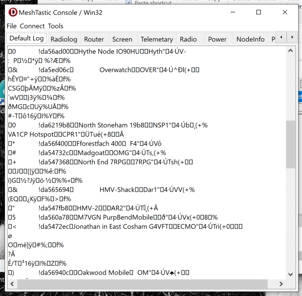
At this point i’m just going to blast that packet back. I don’t like that I dont know what I’m doing. Lets try… Boom, a screenfull of garbage with interspersed text. So we are in packet mode and we got a node list:

Now we in theory have our key to this which we found above. So lets parse this out into packets andthen we can try and do something with it…

I’m going to use a state machine to look for the magic numbers and then pull out the packet length and grab the data. Ironically TRNet doesnt work much different to this, we just have an addess in the header. To make things easier I’ll try and get it printing in Intel hex format too…

Now the 5th byte tells us what a packet is. protobuffs can be nested and I’d urge you to at least go and read up about how they work. Its really quite clever and quite analogous to structs/records and indeed that’s probobly how I’ll deal with this.

Having read what we found above whe have a good ideas what we have here. The 0x22’s are going to be node information so we now need to know what that 5th byte represents. It may represent data, another struct or whatever.

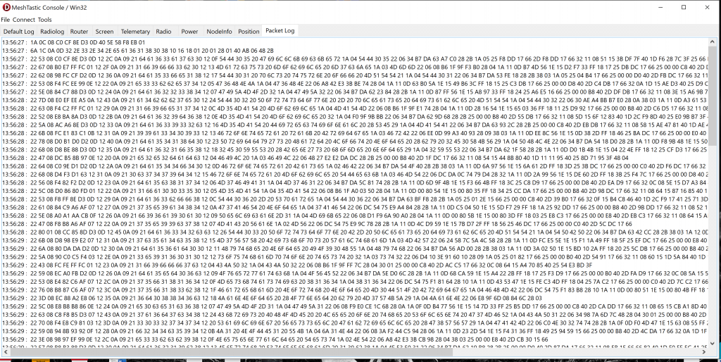
Converting to ASCII we can see we clearly get two packets of unknown function then the start of the node list.

14:11:19 : 1A 0C 08 C0 CF 8E D3 0D 40 5E 58 F8 EB 01 : . . . À Ï Ž Ó . @ ^ X ø ë .


14:11:19 : 6A 1C 0A 0D 32 2E 33 2E 34 2E 65 61 36 31 38 30 38 10 16 18 01 20 01 28 01 40 AB 06 48 2B : j . . . 2 . 3 . 4 . e a 6 1 8 0 8 . . . . . ( . @ « . H +

14:11:19 : 22 53 08 C0 CF 8E D3 0D 12 2C 0A 09 21 64 61 36 33 61 37 63 30 12 0F 54 44 30 35 20 47 69 6C 6C 6B 69 63 6B 65 72 1A 04 54 44 30 35 22 06 34 B7 DA 63 A7 C0 28 2B 1A 05 25 74 E1 17 66 2D 74 E1 17 66 32 11 08 50 15 14 AE 7F 40 1D 4E 1B 34 41 25 15 67 4D 40 : ” S . À Ï Ž Ó . . , . . ! d a 6 3 a 7 c 0 . . T D 0 5 G i l l k i c k e r . . T D 0 5 ” . 4 · Ú c § À ( + . . % t á . f – t á . f 2 . . P . . ®  @ . N . 4 A % . g M @

From this we now know that 0x22 is a node info packet. We need to find out what 0x1A and 0x6A are. This info *should* be in the source code for the Protobuffs and the registry here. The issue is we seem to be missing the root entries. I could be misreading something but there are references to constants for these all over the place but no actual definition of these constants.

BT HomeHub 5a / Plusnet OneHub DDWRT Upgrade Notes

This is more a brain dump for me in addition to the great resources already online.

First up go HERE https://openwrt.org/toh/bt/homehub_v5a
And HERE https://openwrt.ebilan.co.uk/viewtopic.php?f=7&t=266

You’ll need the Uboot image, LEDE boot image and the Sysupgrade image on a USB Stick. You’ll also have need to have done the UART mod detailed on the first page.

Assuming this is going on a live network you dont NEED to use 192.168.1.1 and the server address given. Ad the uboot prompt simply do:

U-Boot> setenv ipaddr 192.168.1.126 
U-Boot> setenv serverip 192.168.1.1
U-Boot> setenv netmask 255.255.255.0

This sets us up using the IP addresses shown. This isn’t stored so if you screw up, you’ll have to start over.

Insert a fat32 formatted USB key into the USB port containing the squashfs image. Issue the following command to boot from your TFTP server

tftpboot 0x81000000 lede-lantiq-xrx200-BTHOMEHUBV5A-installimage.bin; bootm 0x81000000 

Let it boot. When its done mount the USB stick and copy the image to /tmp

cp /mnt/usb/imagename.bin /tmp
mkdir /mnt/usb
mount /dev/sda1 /mnt/usb

Backup the NAND to USB…

nanddump -f /mnt/usb/3998.nanddump /dev/mtd4

This can take a while so go and do something else. I used the last 4 digits of the serial to name the file as I’ll do a few of these. Obviously junk flash drives will make this worse. Once its done, run the prepare script…

prepare

Allow it to do it’s thing and follow the prompts. Once its done we are ready to do the final install. Navigate to the usb drive you mounted and install the image. I had much more luck using the oldest image

sysupgrade /path/to/image/image.img

An important note here, and probobly a reason for a lot of reports of this failing. This will start, do a bit, complain about the watchdog, throw an error and then start running init scripts giving the opinion of a shutdown and halt. If you reboot at this point you’ll stuff the image. Unles it says “nand update failed”, leave it alone. The instructions don’t mention this and they do imply its a quick process. It takes a few minutes and then it WILL reboot back to the CFG prompt. Power cycle and you should be golden.

Installing MS DOS Without floppies

So how many of you old PC collectors have had this one? You are trying to get MS-DOS onto an old PC, you either have no floppies, no floppy drive or both. Sure, getting DOS 6.22 to boot from USB is easy but if you actually want to use the installer, well that’s not going to happen without floppies.

If you search Google there is a wealth of info on how to make a bootable 6.22 USB drive but nothing on how to make the installer work. It needs floppies and you can’t just copy files somewhere and run from that. So, how do we resolve this?

I had this very issue recently. After a protracted fight with an old laptop I got it booted and then I was left with a choice. FreeDOS or copied MS-DOS files from a floppy image with most of the installation missing. FreeDOS has behaved “odd” on this hardware and there are warnings about running Windows under it here. I’ll be running 3.11 on this AND some of my older software which hooks a LOT of interrupts so I’m not feeling comfortable here. I’m also curious as to how well it’ll behave with DPMI overlays for the same reason, everything points to 386 mode being the issue. Sure the basic MS-DOS install works but its missing a lot, EMM386, DosShell, DriveSpace etc so I want the lot. Enter Turbo image…

Turbo image is a TSR (remember those?) That allows you to mount a .img file as a floppy drive, A or B an as far as I have found, everything is happy with this situation. The TSR can be popped up at any time with CTRL+ALT+T and you can change image. It can be found in the old SimTEL archives but a LOT of these are just lists of dead links. It was (at last check) available through archive.org here, and yes, you CAN install MS-DOS with it, with some mods to your boot disk.

I’ve found the easiest way to do this was with virtualbox. You need to be able to mount your install disk 1 image somehow and edit it, and you’ll need to transfer two files to it. One of the files you need is himem.sys from MS-DOS and is compressed on disk 2. In my case I span up a VM, installed MS-DOS from floppy images and then shut everything down. If you are using Widows 10+ you can now add that VHD in disk management and access the virtual drive to copy ti.com from the archive over. Unmount the image and boot into dos in the virtual machine. Re-Connect the first of the three install floppies to the virtual machine and copy HIMEM.SYS and TI.COM over to the first installation disk. You’ll then need to edit the config.sys on the install floppy to load himen (add device=himem.sys) and edit autoecec.bat to launch ti.com. Shut everything down, and you now have your original two floppy images and your now modified image. I’ve also uploaded my modified image here if you don’t want to go through the above. However, if you do and you have to resort to a manual install (Partition and system format the HD from a boot disk), you’ll have the whole DOS file structure to hand.

Now you need those images. You have two ways to do this. In my case I had an empty data drive in the form of a second CF card. The card was formatted IN the target machine to stop Windows doing anything “clever” and then the remaining two image files were copied over. You could also add a small (4Mb) partition to the end of your target drive, format this and copy the image files there. Where-ever you put them they must be visible. you could add CD/ASPI drivers to the first disk and have a CD-ROM/SCSI drive/ZIP/USB drive available for the images. I found the second drive and partition methods easiest as it was far less faff. Also in my case, these were my only options.

Boot from your disk 1 image and proceed as normal, when prompted for disk 2, press CTRL+ALT+T and you’ll get the popup. Select your disk 2, escape and press enter, do the same for disk 3 and you are done. Also, this does the install at the speed of your RAM and target drive, its FAST!

Reboot when prompted and all should be well. So far I’ve used Turbo Image to get Turbo Pascal, DOS and Norton Utilities installed without a hitch. Its definitely one to leave on the machine and the machine I’m working on not having a working floppy is now less of an issue.

Terrafix TVC4000 Notes and Warnings

First up. I do not work for Terrafix, I’m neither an agent or official service tech. I’m simply just another tinkerer trying to keep old tech out of the trash.

Secondly, if you have one of these with full software, you probobly shouldn’t have it. The software is proprietary and tied to the original customer. Unless you have explicit permission, using the original software could be classed as a prosecutable, criminal offence. Most of these units remain the property of the original owner and those that are out there are often only available due to oversight during decommissioning. At best you may be looking at theft or handling stolen goods, at worse a whole slew of other offences under the Computer Misuse act may be added. If you are a medical professional this WILL cost you your professional qualifications.

Thirdly, this is a work in progress and its likely not to get finished anytime soon.

The TVC4000 is an embedded PC specifically intended for use by the emergency services. Its based around PC hardware and has a lot of tweaks made so that it can interact with the vehicle and deal with the realities of being on the road. Vehicles aren’t nice places for PCs. It bundles in 2 serial ports, GPS, WLAN, Wifi, CAN, GPIO, Audio, Networking, one open MiniPCIe slot, Displayport and a GMSL port. Hardware wise it is a pretty aneamic box. An untterly underwhelming Atom N2600 dual core processor is backed up with 2Gb of DDR3. It is supplied running Windows 7 Pro as it stands

Using one as is? DONT!
As you’ll see above this machine has integrated WLAN, 3G/GPRS in this case. This is handled via PPP to present as a network adapter. We all know Windows 7 is not only well past end of life, but has some serious security issues that are wormable. So this box is exposed to the outside world with just the W7 firewall to protect it. Worse the dev box was missing a lot of very, very important updates. If the 3G carrier uses CGNAT then this is still an issue but not as severe as if the system is given a public IP, which some carriers do. If you pop in a SIM from such a carrier this machine is extremely vulnerable and would likely be compromised quickly. Likewise it plugging it into a network take precautions and get the updates on. It’s possible these updates are missing on purpose as they may break something. If you are using one of these in a clinical setting you MUST perform a risk assessment and look closeley at how this all ties in with your data governance and security assessment. Windows 7 automatically means you would not typically be considered compliant, unless you are on LTS there is no way to fix this and these systems should NOT be used for critical or confidential (clinical) data.

Getting it going
So you have one of these and you want to get it going. There is some good news here. These units rarely come up complete so you’ll either have all you need, awesome, or you are going to have to do some cobbling together of parts. If you do have the unit , display and display cable then you are most of the way there. The display and GMSL cables are hard/impossible to find without buying direct. If you don’t have these the Displayport does work as the primary device as do the USB ports.

Power wise you are going to need 12V at about 2.5A. There is an oboard battery that will need to charge and that will trip smaller supplies up. Idle the system uses about 1.7A with an SSD. You will need a 4 pin molex plug as used on many ATX power supplies. Looking at the TVC4000 from the back the top left pin is 1 then follow around clockwise. 1 is switched ignition, 2 is GND, 3 is power and 4 is not used.

When you power the unit up for the first time you may find the unit power cycles but never boots, flashing the red power LED a few times and restarting. This is the result of a low battery. Simply leave it alone for a while and it’ll boot.

From this point its a normal PC with rather limited hardware. If you are starting over without a hard drive then get a good SSD and a stick of 4GB DDR3L and pop them in, it’ll make life significantly better. 4GB is the max this machine will take and you’ll need a 64 bit windows install to go further.

OS Install Time
Windows 7 installs easily enough without any issues. I would expect Linux to work happily but expect some issues with the touch screen and potentially audio. In this situation Linux may be a better be a better fit as it can be secured and updated a lot easier than Windows 7. It depends on your end use scenario. Before you do anything get Chrome installed. This is the most modern browser you’ll get and you will need it as the bundled IE that comes with 7 will fail on almost all websites. Once you have that done you need to start on updates. Getting Win 7 to update is an uphill battle and there is a specific sequence of updates you need to download and apply before you even try to get it updating as follows…

KB3102810 should be the very first and then reboot. After that KB947821, KB3050265, KB3083710, KB3102810, KB311234, KB3138612 and KB3145739. Reboot when asked, don’t try and do the lot in one hit. After that you should be able to run Windows update. The first search may take up to 15 minutes and you’ll have a few GB of updates. To have some fail is normal, just keep going till you are all done. It is possible while it is checking for updates it may grab a few anyway, you’ll see the install updates request pop up on shutdown/restart if it does. It takes a few goes to get it all up to date and it does take a fair while.

Hardware wise all the drivers can be found with a bit of digging and I’ll upload a driver package for the system at some point and link it here. The only fly in the ointment seems to be the 3G WAN driver which falls over due to driver signing. Once the GMA display driver is in the system will be able to treat the GMSL and Displayport displays as separate displays.

Windows 10 needs the 4Gb and ideally an SSD. The Install goes through easily enough though although it isn’t quick, this CPU/Chipset really doesn’t have the bandwidth to exploit the SSD properly although its still faster than spinning rust. You’ll also want to disconnect the LAN cable before you starts and skip connecting to a WiFi network else you’ll be forced into using a Microsoft ID. 10 does find most of the hardware on its own making the install much, much easier than 7. Although the Atom N2600 Cedarview CPU isn’t officially supported it does work just fine. It may take a few passes to get all the drivers and don’t forget to check the optional updates, these are where the drivers will be.

And here starts the first bit of stupidity, graphics. There are NO windows 10 drivers. Hell there are no official 64 bit drivers. This isn’t a huge thing and if you are planning on using this thing as is the default windows driver isn’t actually broken. I’ve seen a few suggested fixed but nothing actually seems to work without blue screens. If you need the dual head support then you will have to install Win 7. *IF* the second PCIe slot is a true slot you may be able to add graphics here. I have personally added full graphics cards to single lane slots and depending on the card, it does work well. You may be able to get Win 10 32 bit using the driver following this guide here.

Take a moment to not only go through and shut Windows 10 up by disabling all the advertising rubbish but pop over to Spiceworks and grab the Decrapifier script here. Arguably 10 brings better driver support, security and usability but it also brings along bundled garbage, lack of control over updates and unpredictable reboots to add “features”. Its a bit of a trade off sadly. I’ve found the best order for installation is Windows, Chrome/Edge then update till it won’t update no more (check for driver updates) and decrappify.

Power Saving
Last but not least, knock out power saving on both operating systems. Windows 7 seems to behave for the best part but the more aggressive power management in 10 seems to cause the odd black screen of death.

Apps to round it out…
So assuming you are at the point where things are working and you have all your drivers its time to… no, not yet. Back it up! Use Acronis or EaseUs and make a disk image to recover from, you will thank me for it later!

Now, lets add some apps…
If you are using 7, as we have already covered, you will need a modern browser. You will also want good anti virus with a firewall, Esset is a good call as its lightweight and isn’t popup happy. Bear in mind the usual home user type solutions are constantly throwing ads or pop ups and this isn’t what you need in this situation.

If you are planning to be able to test and troubleshoot the system you’ll want Putty, Ublox UCentre, Visual GPS View, Ublox MCentre and CANKing. These should cover most things you might want to do. I don’t know of a way to test the GPIO pins, there is an official Kontron package but it requires subscription.

If this is going into a vehicle you’ll want to drop Mapfactor Navigator on there. This is a VERY capable navigation system with a lot of extras designed just for this sort of system. I’d urge you to give these guys some cash, for what this program is, it’s not expensive. Centrafuse is also worth a look for less commercial uses and integrates with pretty much everything

So in summary, both OS’s are compromises, 7 with security and 10 with the display driver. If the second display isn’t an issue then its an easy win for 10, however you’ll pay the price for this in a slightly slower system and needing more RAM. If this is an issue then use 7 but bolt it down. Either of these you should be looking at an external 4G modem anyway. Most of these will work happily with the antenna already on the vehicle.

Cisco SPA232D and FreePBX

This is a quick guide, mainly for me and as a reference. Getting this to play ball on Chan_SIP was a breeze. PJ_SIP breaks this somewhat. The guides I’ve found are focused on pure Asterisk and/or Chan_SIP. This is what I had to do to get this to play ball and work. This is for UK installations so if you aren’t in the UK or US (Defaults work for the US/Can) you will need to find your localisation settings yourself…

I’ll assume the unit has been factory reset, instructions for this are at : https://www.cisco.com/c/dam/en/us/td/docs/voice_ip_comm/csbpvga/spa100-200/quick_start/SPA232D_QSG-en_78-21580-01.pdf

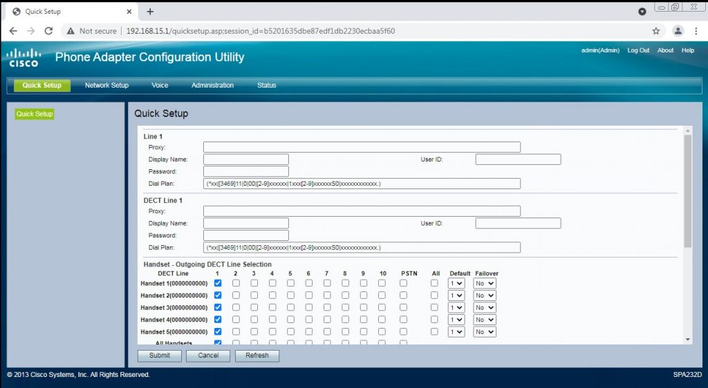
First up. We need to setup the network side of things. Plug a PC into the LAN port of the 232 and make sure you get an IP address. Don’t just plug one of these into a LAN as they run a DHCP server. Login to the web UI as admin/admin…

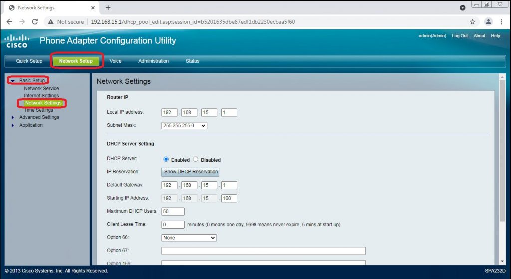
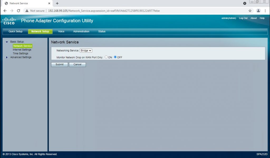
A few sites mention using the LAN port will cause issues, and left at the defaults it will. We need to disable routing and bridge those ports. Click ‘Network setup’ from the top options, then ‘basic setup’ from the side. Under the new options pick ‘Network Settings’

You’ll need to disable the DHCP server. Click the ‘disabled’ checkbox and hit apply. As long as you do the next step quickly you don’t need to make any networking changes to your PC. If you allow the lease to expire, you’ll need to set a static IP for your PC on 192.168.15.0/25 to continue. I’ve never had to do this.

Click ‘Network Service’ and change the dropdown to ‘Bridge’. Submit the change and the unit will boot. As your PC won’t ever see the network drop it may not renew your IP address.
Once the SPA has rebooted your WAN and LAN ports are connected to the same network. Either place the SPA on your main network now where it’ll get a DHCP address and reconnect your PC to your LAN or stay plugged into the SPA, it doesn’t matter at this point. It helps to know the MAC printed on the SPA if you have more than one device at this point. Log into your router or firewall/router and check your DHCP lease table / list of known devices and find where your SPA went…

If you have more than one SPA device, use the MAC to identify it. You can then re-connect with your web browser to the new address. This set of steps removes the need to go through allowing remote access and stops a layer of NAT being added to a protocol which, quite frankly, hates NAT 🙂

Before you go any further check Administration => Firmware Upgrade. Make sure you are running 1.4.1, if not click here to go and get it and update the SPA. If you don’t you may have issues with getting a 202 error making outgoing calls. The latest (and last) firmware fixes this.

I’ll now run through each page, I’ll highlight where we are changing defaults and list the changes. If I haven’t touched a field the default is just fine. Hitting submit can, depending on the screen, reboot the unit or take a while to return.


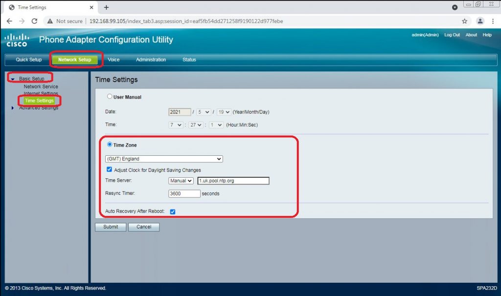
Select Network Setup=> Basic Setup, Time Settings

There is probobly no pressing need to do this but if you want to later use TLS, or the debug logs it’s worth doing. Set your timezone, time server and enable “Auto Recovery After Reboot”. Hit “Submit” and wait for the UI to return.

Voice => System, SIP and Provision have nothing to change.

Voice=> Regional

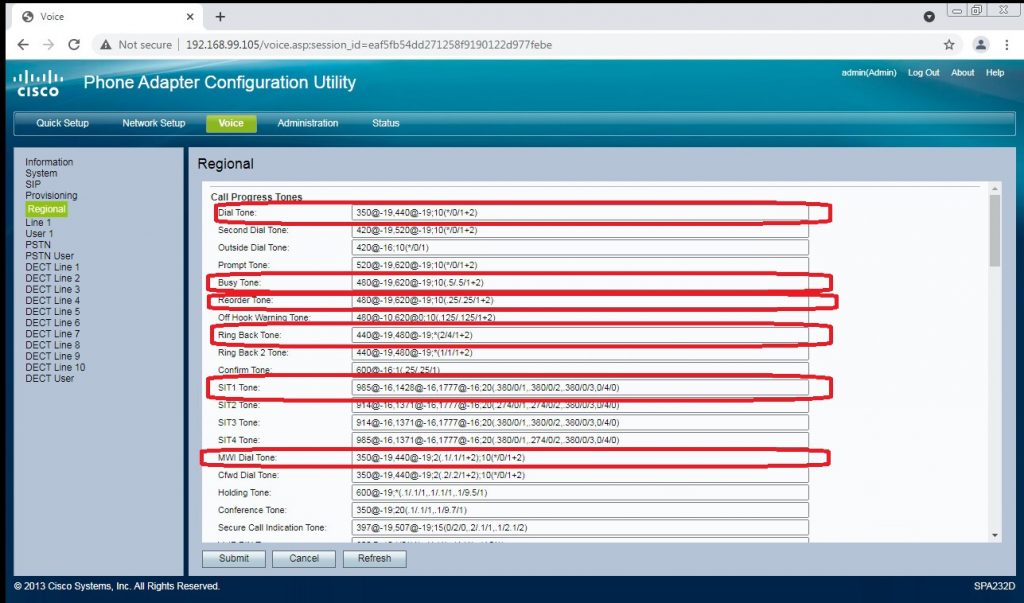
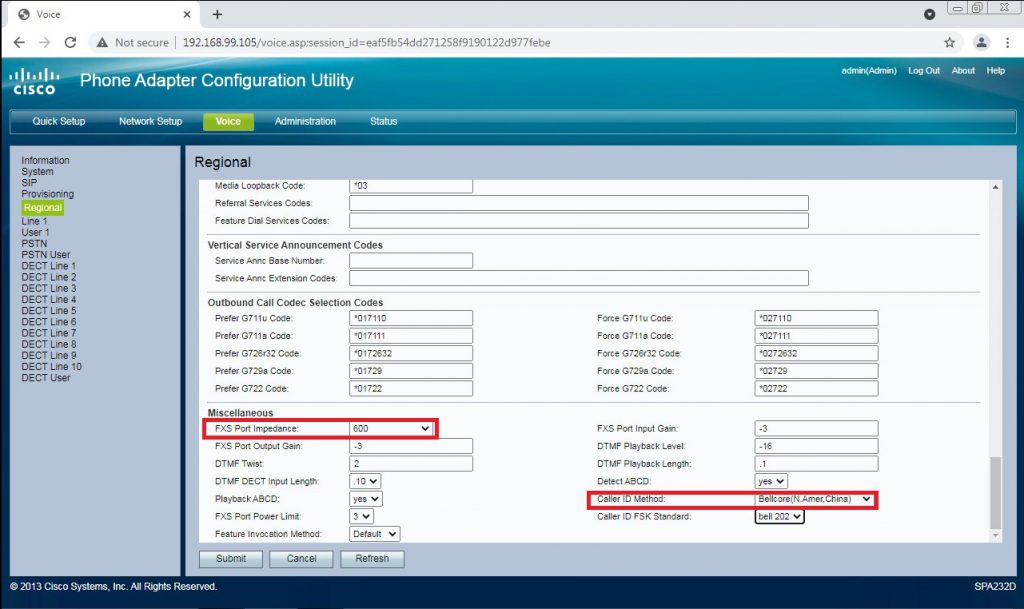
There is a fair amount here and you need to get it right or your SPA may act up. BT aren’t totally consistent across exchanges and though most of the defaults here will work, on some exchanges you may se issues with caller ID and call termination if you don’t change these… snarfed from here

Note this screenshot shows the DEFAULT values. New ones below to copy and paste
Voice > Regional > Call Progress Tones
    Dial tone: 350@-19,440@-22;10(*/0/1+2) 
    Ring back: 400@-20,450@-20;*(.4/.2/1+2,.4/2/1+2) 
    Busy tone: 400@-20;10(.375/.375/1) 
    Reorder tone: 400@-20;10(*/0/1) 
    SIT 1 tone: 950@-16,1400@-16,1800@-16;20(.330/0/1,.330/0/2,.330/0/3,0/1/0) 
    MWI dial tone: 350@-19,440@-22;10(.75/.75/1+2) 
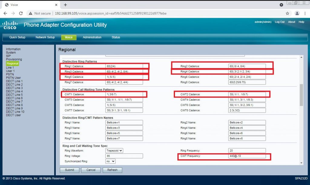
Again, this shows the DEFAULT values, new ones are below.
Voice > Regional > Distinctive Call Waiting Tone Patterns
    CWT1 cadence: 30(.1/2) 
    CWT2 cadence: 30(.25/.25,.25/.25,.25/5) 

Voice > Regional > Distinctive Ring Patterns
    Ring 1 cadence: 60(.4/.2,.4/2) 
    Ring 2 cadence: 60(1/2) 
    Ring 3 cadence: 60(.25/.25,.25/.25,.25/1.75) 
    Ring 4 cadence: 60(.4/.8) 
    Ring 5 cadence: 60(2/4)

Voice > Regional > Ring and Call Waiting Tone Spec
    CWT frequency: 400@-10

Voice > Regional > Miscellaneous
    FXS Port Impedance: 370+620||310nF (or 270+750||150nF ) 
    Caller ID Method: ETSI FSK With PR(UK)

Note the two fields for gain here. As they stand they are normally ok but we have had to tweak these on longer lines. A little is a lot though so be careful. Submit your changes and wait for the UI to return.

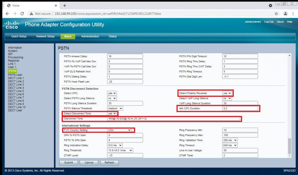
Again these are the defaults, new values below.

Voice => PSTN

Scroll down to the bottom of this page. We will be back here in a minute but we need to make these changes…

Voice > PSTN > PSTN Disconnect Detection
    Detect Polarity Reversal: no 
    Min CPC Duration: 0.09 
    Detect Disconnect Tone: yes 
    Disconnect Tone - 400@-30,400@-30; 2(3/0/1+2)
Voice > PSTN > International Settings
    FXO Country Setting: UK

Click submit and as far as UK setup goes, you are done.

You will need the CID for this line and to set a password. The CID is used for call routing and the PJSIP setup rather than a username, you have a little less flexibility here than Chan_SIP and mistakes here will make this behave in odd ways.

Voice => Line 1

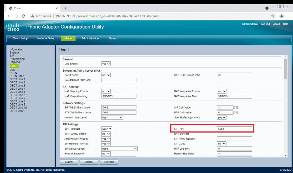
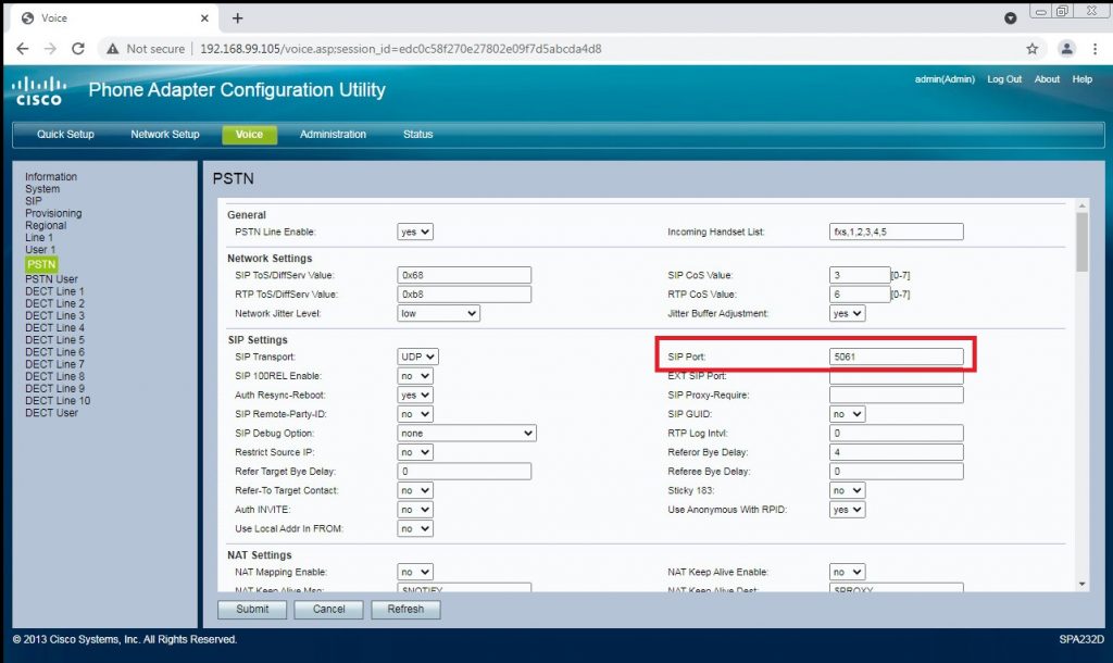
Change SIP Port to 5060, these are (for some reason) reversed between this and the next page. They *should* be different and this caused no end of headaches until someone elsewhere pointed out the documentation is wrong. Prior to changing this we were seeing calls out fail with channel unavailable and the cause given as incomplete number supplied.

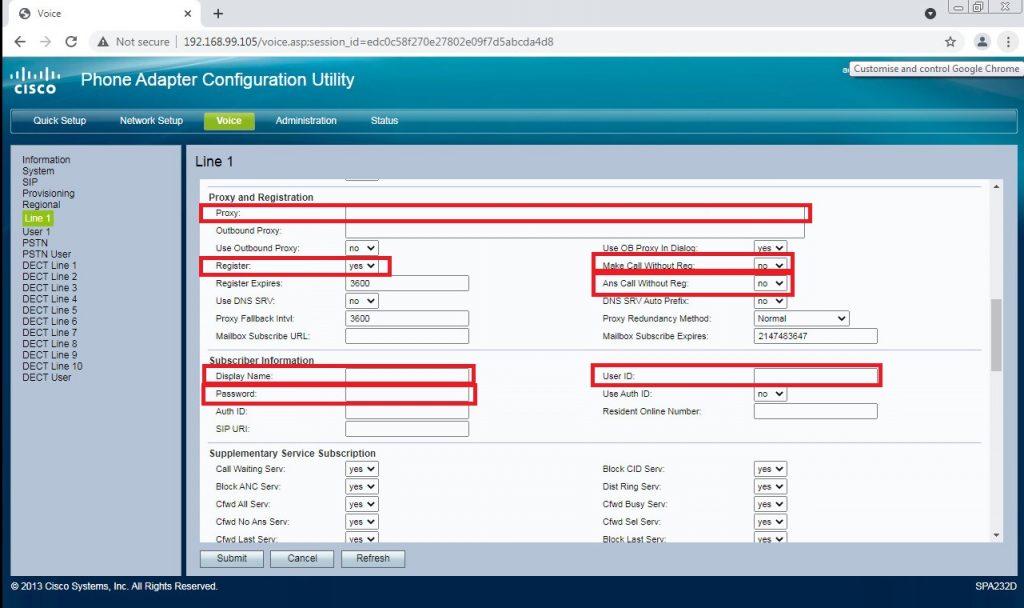
Again, these are the defaults…

Proxy & Registration
Set the proxy to the IP of your Freepbx Server. Change “Register” to no, “Make Call Without Reg” and “Ans Call Without Reg” to yes.

Subscriber Information
Set “Display Name” and “User Id” to your DID. These must match the PJ Sip trunk name we will create in a bit. There are some odd UI behaviours setting these up in FreePBX, this just makes life easier for all. Password is what you’ll set in Freepbx for this trunk so set these and keep them for later.

Hit Submit and wait for it to come back, we are halfway there.

Skip User 1 and we want to be in the PSTN settings now…

SIP Settings

Change SIP port to 5060. Again not quite sure why this is needed and why so much documentation has it wrong, but it seems to be what really upsets PJSIP.

Again… defaults

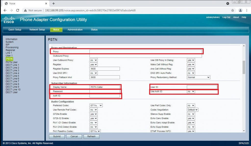
Proxy & Registration
Set Proxy to the IP address of your Freepbx box. Display name, User Id and Auth ID should be your DID and Password the one you already used. A few guides say it is important to leave display name blank. Again doing so seems to occasionally trip PJSIP by mangling headers.

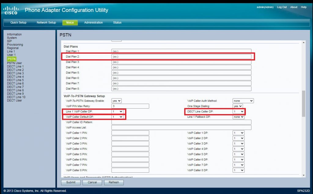
Dial Plans

Leave Dial Plan 1 alone. Set 2 as follows. Watch the brackets!

S0<:123456789@127.0.0.1>

Change 123456789 for your DID. This is what will be matched for your inbound route. You can change this to anythign you like but typically trunks are matched on the DID and Freepbx has limitations on the DID field. Keep it simple! 127.0.0.1 should be replaced with the IP of your freepbx box.

Voip-To_PSTN Gateway Setup
Set Line 1 Called DP and Voip Caller DP to none. Not sure why I highlighted the DECT one, we aren’t using it.

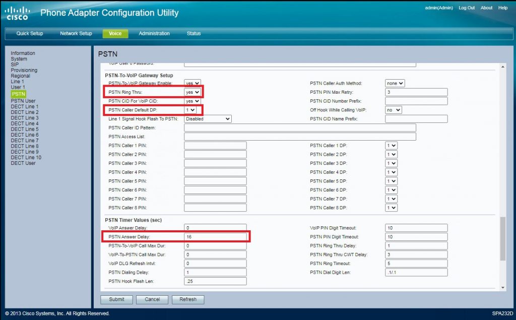
PSTN-To-VoIP Gateway Setup
Set PSTN Ring Through to no. This is personal preference but can help mask the occasional appearance of two ring tones after dialling. PSTN Caller Default DP changes to to, pointing at the dial plan we created earlier to route the call to Freepbx.


PSTN Timer Values (sec)
Change PSTN Answer Delay to 1. This is how many rings before the FXO seizes the line. There is anecdotal evidence that while 0 works it can cause some odd race conditions. We have set everything else we need to now, so hit submit and wait for the reboot.

FreePBX
I’m only going to cover getting the trunk setup. Routes etc are down to you. If you’ve followed my example and used your DID you’ll be able to match on this. No Pictures here as I don’t want my PBX info all over the net 🙂 Maybe I’ll redo this with a lab setup.

Add a new PJsip Trunk. Name your trunk as your DID. Set your caller ID to match your DID and max channels to 1. Everything on “General” stays on defaults

Under PJsip settings…
Authentication to None
Registration to None
SIP Server is set to the IP of your SPA, this is where you may want to set a static IP for it.
SIP Server port is set to 5060

Under the advanced tab set:
Permanent Auth Rejection to Disabled (Unchecked)
Forbidden Retry Interval to 10
General retry Interval to 15
Expiration to 60
Max Retries to 10
Qualify Frequency to 15

Submit then apply settings. If you’ve had calls while setting up you *may* need to go check the Intrusion Detection module and make sure your SPA hasn’t been blacklisted.

I realise there are almost certainly settings that don’t need to be changed here BUT this is a copy of what eventually worked for us. The whole thing seems way more picky than CHAN_SIP but this setup does work. I hope it helps someone.

Making DOCSIS config files under Debian (8)

This is a really quick brain dump so I remember what I’ve had to do to make this work. This is to get DOCSIS files to work with an Arris CMTS100 and old NTL (ambit) 250 modem.

There is a free windows app here to do this but I just got errors from the CMTS from it. This may be my fault or something else but the Linux DOCSIS program seems to be much more consistent, it’s not tried to abstract everything too much and allows finer grained control and decoding of the DOCSIS files.

You’ll need to grab the source from here which includes a link to example files. You’ll need all the usual development packages, GCC, Make etc. You will also need to download and compile net-snmp from here. I also had to make a symlin to my libperl.so on the dev box (ln -s libperl.so.5.20 libperl.so) to get net-snmp to compile. The instructions for doing this are here. You will also need to make sure you have Bison available. You will need libsnmp-dev and flex, neither of which the configure script will tell you are missing if you try to run it. If you are good at this point you can unpack the source and do a ./configure and all will be good. So in my bare Debian 8 dev box…

apt-get install gcc make flex bison libsnmp-dev -y
./configure
make all
make install

You should now be able to type “docsis” and get help.

In use we have a text file that has our config and another with our key for the CMTS….

docsis docsis.txt key.txt docsis.md5

H50B-IC LCD Touch HMI Module. Getting It Working

Some of you may have seen these modules on Ebay, Wish and Aliexpress. On the surface they seem a really good way to get a full colour GUI with touch on something fairly low powere. These will work with a low end PIC or Atmega but I’m working with a Arduino Mega and STM32 here.

An example can be found here (as long as the link is live) and i looks like this :

The specimin in questio

SO on paper this looks like a good bet, it works over I2C, you have a designer application for it, its full colour, a good resolution and in theory all you have to do is update content and process events. Perfect for what I need to do. It even comes with a datasheet, programming cable, examples and software…

Well, thats sort of true, you get the display, a cable for programming (CH340 USB dongle) a cable for connecting it and that is it. There isnt even any demo code loaded so powering it up will get nothing. The vendor didnt reply to requests for help so off to the net I went. and found that this is a common issue. The manufacturer is Hunda Tech and if you pop over to here you can find an almost useless datasheet for it and right at the bottom there is some Arduino examples. There is no sign of the Visual LCD Studio that you need to actually edit the stored displays. You can find this in this archive here, this includes the software, examples, english datasheets and much better documentation. You should be able to get started with this archive.

BUT…

The application is buggy and complete garbage. It really is a prime example of fire and forget software. Save often, do not leave it open (It leaks memory) and expect it to crash with no warning or hope of recovery if you haven’t saved. Many controls do not behave as expected and as for the help… One of the biggest bugbears is auto control numbering, it has a ‘fencepost’ error and will cause compile errors