Category Archives: Uncategorised

UK Use of TETRA Radios for Commercial Use

This is a slightly more in depth look into the realities and legalities of using surplus TETRA kit in the united Kingdom. This deals ONLY with commercial use and not use by Radio Amateurs. Much of this applies to HAM use but there are a few exceptions where you CAN use these radios. However as is made clear in your licence you may not do so for commercial use.

The information in here is sourced either from other sites (I’ll try and link these in) or direct from OFCOM. Remeber before trying to argue the toss that it is actually OFCOM that has the final say.

And of course the caveat. I am not a lawyer, I don’t know your kit, I don’t know where it came from or how you intend to use it. This is a GUIDE only and nothing more. At the end of the day it is your responsibility alone, not mine, not the vendor who sold you the kit, to make sure what you are doing is legal and complies with the terms of your licence.

A little about licences…

In the original post I didn’t cover this at all, this lead to some confusion. You’ll likeley already have a business licence or be thinking about one. You’ll be looking at one of a number of options…
* Simple Light
* Simple Site
* Technically Assigned
* Area Defined
Suppliers Light is a very different kettle of fish but as a rule it doesnt get around the limitations discussed here. It buys you some more wiggle room but there are other restrictions.

Technically assigned and Area defined have changed a little and are seriously expensive if you start going mad. For the purpose of this I’ll be concentrating on the first two, that’s what the majority have and to be fair, if you have THAT much money to throw around on technically assigned or area defined there are some more avenues open to you.

There is one other avenue that makes this whole article moot. It is possible to obtain permission to access the Airwave network. For emergency organisations you may apply as a few have done including The Red Cross. However as a commercial entity allow a suitably large sum for network access and then per handset. It’s unknown if Airwave allow the use of your own equipment.

Your licence will give you more guidance, however typically you’ll get the following conditions: (Ive omitted bands that are of no interest)

Simple Light (Or just Simple)
Maximum ERP of 5W
No use of Base Stations
5 Allocations in the Low band (77.6875 – 86.3750)
7 Allocations in the VHF Band (164.0500 – 173.0875)
3 Allocations in the UHF Band (449.1325 – 449.4750)

Simple Site
Maximum ERP of 2W
Use of Base stations subject to above ERP Limit
16 Allocations in the VHF Band limited to .02W (159.63750-164.2000)
17 Allocations in the UHF Band (459.0500 to 459.47500)

Licence Free Bands

There is also a licence free band called PMR466 we need to bear in mind. The controls on what is allowed in this band are very strict. The band runs from 446.000 to 446.200 as twelve channels and another groups below this at 434.040 to 434.790. The requirements for this are availabe in some detail here, but one thing for our purposes is very important; “PMR446 users are reminded that their radios are only licence-exempt if they are built and operated within the conditions of the exemption regulations.” So this automatically rules out the use of ANY TETRA handset in this band. That was easy, no ifs, buts, just don’t! The details on this are here

Tetra Bands

Sepura and Simoco, the guys that started this decided that rather than this messy LF/HF/VLF/UHF/VHF mess they would use a simple two letter identifier to identify what bands their devices can use. If you check the model of your radio online it’ll give you what the capabilities are. You can sometimes also identify this from the hardware code where it’ll be the forth and fifth letters. The bands are as follows:

TG – 400-433Mhz
TL – 368-400Mhz
TN – 380-414Mhz
TR – 350-372Mhz
UO – 440-473Mhz
XB – 851-870Mhz
TZ – 410-430Mhz
TS – 370-400Mhz
TW – 380-430Mhz
TT – 380-400Mhz
UW – 407.473Mhz

So a quick look and we can write most ot his lot off right away. The Lowest we are realistically going to go on our licences is 449MHz. This means we are looking at UO or UW. Hams can in theory get away on the extreme edge of TZ and TW and a Technically assigned is possible to, but this is the extreme limit of the radio and a bad idea.

This is where it starts to really go wrong. Let’s look at what lives in those bands, you can look yourself here.

368-406 is pretty much all MOD, you REALLY don’t want to be in here!
406-430 is a mixed bag but mostly MOD.
UK Airwave allocation starts at about 380Mhz up to around 410. Dolphin had allocations in 425-430 and there are some D700 and D1700s still kicking about! All of this is in MOD space and “leased” to Airwave.
430 is Amateur (70cm) band. You don’t want to be here, if anything if you start upsetting Amateurs you are MORE likely to get caught!
There are more Tetra channels splattered about above here used by Connect (TFL) then into the licenced bands above. PMR466 on top and then we run out of band for all but XB. For giggles, XB is mostly pagers and Mobile phones.

So frequency wise, you have UO and UW as your options. The use of ANYTHING else simply isnt legal. UW sets are few and far between, I’ve never even seen a UO set. Almost everything on the market is TZ or TW and there is no way you can legally use these, no way, no how UNLESS you have specific permission from Airwave or Connect.

Caveat – As mentioned there ARE some Technically assigned frequences around 430Mhz, these are limited, first come first serve and expensive. You are also right on the radio’s limit so it’s really not recommended.


UK Back to back, DMO, TG1, Licence Free ETC

We’ve seen these mentioned a few times by sellers implying that you can use the radios they are selling exempt. The only exempt band in range of the frequency sets we have found legal to use specifically forbids the use of equipment not specifically designed for it. Even if it didnt the power of most TETRA sets is way over the allowed limit and they breach the band use conditions in other ways. Simply put, there is NO WAY to use these licence free.

Why Bother?

So you have found some UO/UW sets, you are thinking about buying them, why?! There is no good use case for these on the licences we have covered. If we assume you have a Simple licence you can’t have base stations, that in itself removes the big reason for using TETRA handsets.

The handsets are designed to be used in range or a repeater in a vehicle or reasonable range of a relay/base unit. These are scattered all over the country and the radios can use any nearby vehicle base to jump onto the network. This leads to the second issue. You cant use any bases or repeaters so you are stuck with the handset’s output. Looking at one of the most common radios, the MTH800 we run into an issue. The rated power of this radio tops out at 1.8W with most running at just 1W. Although thats in the realms of your maximum for a Simple Site licence its significantly less than you can do on a Simple Licence. A quick search throws up ONE UW handset, the STP8040 which likewise tops out at 1.8W at £250 + £30 shipping from overseas. In comparison a good DMR (Motorola) can be had for under £100 from the UK and gives you 5W of RF power and the same security or more. Without a TEA module you can’t use the encryption feature of the handsets, that means your voice is transmitted as PCM data which is trivial to recover with a £30 USB dongle and a laptop. Most DMR radios CAN encrypt data properly.

Finally TETRA is built around the ability to pass data around the network, trunk out to the phone network and proivide many other features you just cant use without a full blown network, it’s not JUST a radio system. The use case for these is poor to say the least. In fact for the cost of that one handset you could have four good quality, solid analog units.

DCS/DMO/CTCSS and TETRA

Tetra and its relative MPT1327 assume exclusive use of a channel. The systems work differently but neither of them play well with other channel users. As part of your licence you have a duty to minimise disruption and the use of CTCSS, DCS or DMR codes is mandatory. We routineley run into whole swathes of spectrum rendered unsuable due to people not doing this. Where the majority of your transmission is data (as is the case with both) you’ll often cause the decoders on on the radios of other users to open meaning they get a blast of your data. It also means your radios will be unable to mitigate a congested channel properly so as well as driving other users up the wall there is no gurantee your radios will even work (Especially true of the MPT1327 control channel)

Legalities of Sale

If you are selling a TETRA radio with an active TEA and valid Airwave programming you are comitting a criminal offence, one that is highly likeley going to result in jail time. Most of these devices are trackable and if they have registered on the airwave network then they know where it is already. If you happen to end up with one of these units as a result of a surplus stock purchase or auction you need to contact Airwave imediately. Turn the radio off and call them. In the event you find one laying about dial 101 and arrange to hand it in. Don’t be tempted to use it.

Things go a bit grey after this. OFCOM don’t care about the sale of these devices and by selling of buying one you arent committing any specific criminal offence although the guide linked below does open the question of aiding and abetting the committing of an offence. It would be questionable in the eyes of Trading Standards were you to sell one intending it to be used, especially if passed off as licence free or legal to use. OFCOM have ben quite open about working with Trading Standards on this issue. The best bet here is speak to OFCOM, if they can be used they should be able to tell you, if not your only real option is to sell them as non working film props or if you are lucky enough to have the right ones, to Radio Amateurs.

What’s the Risk?

First up there is the side effects of actually using these radios on frequencies you shouldn’t. There is the obvious risk that you may cause interference. For some users that is going to cause annoyance and disruption and will in time lead to the issue being referred to OFCOM. However in more serious cases you may disrupt the Airwave network or Military comms in the local area, the potential is there to cause serious damage or loss of life.

Secondly, a lot of this spectrum lies within the MOD’s remit. The MOD are notorious for their lack of sense of humour when it comes to their spectrum space. I personally have experienced this as a result of pointing a Band C doppler radar in the wrong direction. They are very proficient at tracking down the cause of issues and making it stop. This at the very least is going to involve you doing a LOT of explaining before the decision is made to charge you or hand you over to OFCOM. Disrupting Military coms is a very bad idea!

And Thirdly there is OFCOM. They are well aware this equipment is out there and being used illegally. Officially you are likely to be looking at a large fine and the loss of your equipment, often the fine is based on the amount of illegal kit in use. However there is no upper limit and up to two years jail time is also on the table. At the time of writing there have been three local seizures of non compliant TETRA Equipment with 5 digit fines involved.

You have been warned!

Links

Sepura Bands

OFCOM: Radio Spectrum and The Law

OFCOM: Business Radio Licencing


Avaya 9640G Sip Conversion

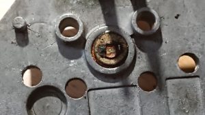
We just came into posession of a number of these phones. They are bulky but the layout is nice and clean, they are solid and it would be nice to use them. As with many Avaya sets these are setup for h232 so we need to get these on SIP and programmed. Thankfully Avaya still have the files available so let’s get going…. This will be quick and dirty as its more an aide memoir for each step.

You’ll need a HTTP server at the least and control over the DHCP server. Our Lab is FreePBX and PFSense so this is easy for us.

So first up, reset the phone to defaults. The default password is “CRAFT” but if your phones have another set you may need to do some digging on how to wipe these. I have reset over 100 of these in the last few days and no one had a non default password so the odds are good.

Power up the phone (We used POE) and wait for the DHCP prompt. Hit * and enter the password above (27238). Select clear and let it reboot.  You’ll need to go back into that menu again and scroll down to “SIG”. Change from Default to SIP.

If you are doing just one phone…

Go into ADDR and set the http server to the IP of your web server and then exit and let it reboot (Again), you should now get an error on the phone, “HTTP: 1 -401”. On your web server in the error log you’ll see something like :  [Tue Mar 12 11:54:54 2019] [error] [client 192.168.223.133] File does not exist: /var/www/html/96xxupgrade.txt

If you have a few to do you can use DHCP option 242. Set it as type string and pop in your HTTP server address and some vlan info as follows:

L2Q=1,L2QVLAN=0,VLANTEST=0, HTTPSRVR=<youserverip>,HTTPDIR=/<httpdir>/

Now it DOES seem if doing things this way you CAN specify a directory (see below for why I mention it) and this does work, I’ve verified it. Having made the procedure below work I had a large number of these to do and I was buggered if I was doing them all by hand.

You’ll now need to upload the contents of the firmware from ftp://ftp.avaya.com/incoming/Up1cku9/tsoweb/9600/05152017/96xx-IPT-SIP-R2_6_17-172303.zip

There seems to be no way to tell it where to look on the server doing it manually so sadly, this is going into your web server root unless you use DHCP option 242 as above. It may be possible to to clean this up with virtual hosts of you are so inclined. In my case I took out all the languages I didn’t need.

Either method, you now need to reboot the phone and it should trundle off and update itself. This can take a while and the phone may seem it has died or gotten stuck, be patient. It’ll reboot a few times.  Once it boots the UI is noticeably different, you’ll getr a complaint about no call server and it’ll go into a boot loop. Press the program key when offered to break the loop.

You’ll now need to sort out a settings file. Create the file 46xxsettings.txt in the same location as the other files you uploaded. Pop the contents below in this file BUT make sure you edit things to reflect your setup…

SET DNSSRVR 8.8.8.8
SET DOMAIN <SIP SERVER IP>
SET SIPDOMAIN <SIP SERVER IP>
SET SIPPORT 5160
SET SIP_CONTROLLER_LIST <SIP SERVER IP>:5160;transport=tcp
SET SIPREGPROXYPOLICY alternate
SET CONFIG_SERVER_SECURE_MODE 0
SET SIPPROXYSRVR <SIP SERVER IP>
SET SIPSIGNAL 1
SET SIP_PORT_SECURE 5161
SET ENABLE_AVAYA_ENVIRONMENT 0
SET DIALPLAN [2-8]xxx|91xxxxxxxxxx|9[2-9]xxxxxxxxx
SET PHNNUMOFSA 4
SET SNTPSRVR <NTP SERVER IP>
SET GMTOFFSET -5:00
SET DSTOFFSET 1
SET DSTSTART 2SunMar2L
SET DSTSTOP 1SunNov2L
SET DISPLAY_NAME_NUMBER 1
SET SIG 2
SET HTTPSRVR <HTTP SERVER IP>
SET MSGNUM *97
SET ENABLE_EARLY_MEDIA 1
SET RTP_PORT_LOW 10001
SET RTP_PORT_RANGE 9999
SET SIG_PORT_LOW 5160
SET SIG_PORT_RANGE 1

Note the port, 5160! If you are using CHAN_SIP exclusively or its an older freepbx change this to 5060. If you are on a newer install you’ll need this set to 5160 if PJSIP is your primary channel driver. This is yet another device in the LONG list of things that just don’t play ball with PJSIP. If anyone can make it play please let me know but for now it seems its yet another thing that’s been broken.

Regardless of which port you use, you’ll need to enable TCP for CHAN_SIP. I was able to make this work with UDP, however it was acting up, a little digging shows that this is known to be an issue.

Restart the phone and you *should* get prompted for your username (Extension number) and Password (Secret)

Log in and you should be good.

There is one really handy feature with these, press the menu button and you can logout… this make these phones potentially useful for hotdesking!

Now there are a few other things you can mess with , the settings file is dealt with in depth in a few locations, https://www.3cx.com/community/threads/avaya-96xx-9620-phones.11168/ does have a pile of info on these. There are some known limitations and you can make things play ball a little better if you don’t mind recompiling your freepbx instance, this is covered here: https://community.freepbx.org/t/avaya-96×1-extended-features/40543

DHCP Options are covered here : https://downloads.avaya.com/css/P8/documents/003876932


Fritzbox 3370 Flashing (Hynix)

So Karl over at TRC got one of thes in for us to look at using with customised OpenWRT/LEDE firmware for a large project rolloput. On paper they are perfect and have all we need. Ok we cant use the DECT radio but hey.

SO a quick look over at https://openwrt.org/toh/avm/fritz.box.wlan.3370 and this should be easy. Got the UART header soldered in, I have the bnoot process stopped and ready to go….

Crap!

As is usually the case with OSS the documentation is a little poor. Starting with the fact that the supplied Image on the page is one file, and then the instructions go on about needing to upload two.

More searching just initally found more complaints of the same 🙁

I did eventually find Micheal Kuron’s blog at https://blog.michael.kuron-germany.de/2018/12/openwrt-on-avm-fritzbox-3370/ which then gave a better link for formwares. the are snapshots so up to date too. The link for these is http://downloads.openwrt.org/snapshots/targets/lantiq/xrx200/

Make sure you get the right one. As detailed on the OpenWRT and Micheal’s page the manufacturer of the flash chip matters.

Now, off we go a’flashin….

Well broadly speaking, it all works, but there is a big gotchya here that I don’t see mentioned anywhere. Don’t use the Windows FTP client. There is no way to put this into passive mode. It’ll simply tell you the cammand isnt known (PASV or Passive) and then *if* you press on anyway you’ll soft brick the router. You won’t be abl;e to do anything until you can get a firmware uploaded. I simply moved the files onto a USB stick and booted a Mint Live distribution which worked just fine.

R

Range Rover P38 Blower Module Servicing and Repair – Part 3, How it works, Failure points.

So you want to know more…

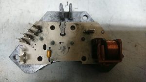
The module is not just a switch, if you have it in bits you’ll have noticed there is a little more going on and there is that odd disk too…

What seems to be going on here is that there is a little bit more than just mdulating the power to the fan. Rover wanted to avoid sontaneous combustion of the blower motors too. So there are two more parts to this story.

First up is that disk again…

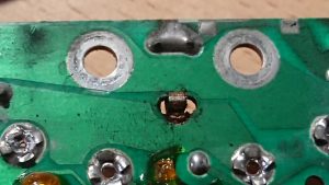
This is a device called a PTC. This is used by the HEVAC ECU to know how hot that heatsink is. Excessive heat can signify a serious failure, a stuck fan or an overload condition. At this point the ECU can kill the drive to the fan. This simply wired between one of the multi plug pins and ground. However it isnt soldered and relys on contact with the heatsink and that spring contact on the board. A bad contact *could* lead the ECU to summise that there is something amiss and shut the fan down. Its certainly worth giving it a clean if you are doing the transistors.

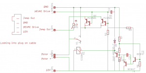
Above is a circuit diagram of the module. Values and compnent names aren’t correct as I just wanted a schematic. I beleive this is correct, although I wouldnt reccomend trying to reproduce it (yet, more later)

The PTC is R1 and as you can see, it simply feeds back to the connector.

The drive transistors are Q1 and Q2. These are in the negative supply to the motor, you’ll also see there is a relay, K1 accross these transistors . You can also see these transistors are in parralel to each other and the failure of one will take out the other.

The drive signal goes right to the transistors but it also goes to the circuitry on the right. When the drive signal reaches a specific value this circuit powers the relay up running the blower at full speed. The reason for this is that there will be a voltage drop over the transistors, even when driven fully on. The relay activates and connects the blower direct to the power supply thus taking this drop out of the circuit. This is the reason that with many of these that fail they will work on full power. Converseley a failure in this circuit or dirty relay contacts could cause loss of full power.

The transistors would normally fail open circuit, in the event they failed short you could end up with a fan jammed on full, however an overload failure would typically annihalate them so it’s unlikeley. The P38’s electrical system does constantly monitor the state of sub compnements so it’s also mot impossible that in the event the blower malfunctions the BECM can kill the aproproate relay (RL6 or RL7)

So what could be done to improve this?

Semiconductor technology has come on a fair way since these were designed. The first job would be to change the transistors to a new type known as a MOSFET. These devices have a much lower voltage drop accross them meaning they generate much, much less heat and place less demands on the driving electronics. It may negate the need for the relay making the whole thing much simpler.  Simpler and cooler means a longer life and potentially better system performance. With the lower heat load it’s also possible this could be remade as an external module to save dismantling a faulty blower provided the motor is fine. It may be possible to change the transistors in the module to MOSFETs as it is with minimal changes.


Range Rover P38 Blower Module Servicing and Repair – Part 2, The control module, dismantling and replacing switching transistors.

So we now turn our attention to the module.

So time for a little warning here. If you want to follow along or are planning on repairing your module be warned, some of what you are going to have to do cannot be reversed. The module is riveted together and you’ll need a good soldering iron. If you make any mistakes here you could kill the module. Its not a complex bit of kit but you could damage the HEVAC panel.

This is the switching module we mentioned in part 1 and takes the place of the resistor pack used in manual systems. The two large metal cans are the transistors used to do the switching and they do fail. Rover used two to split the load over both but one can fail and result in the second failing instantly from overload.

To get in and replace these you’ll need to drill the rivets out from the top (side with the cans). Carfull punch the remains of the rivets out as they hold the PCB on too. You will need to replace these later with bolts.

Flip the board over and desolder the two legs for each transistor. Use a good iron and a solder sucker. Once you get the pins clean the transistors will drop from the heatsink.

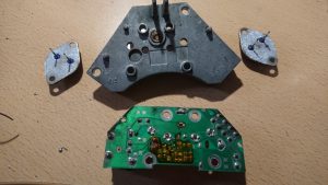
Replacements *can* be found, they are Motorola T1829-1 which are PNP Power Darlington devices. However you’ll be looking at used parts or new old stock, they aren’t easy to find. A drop in replacement is the MJ11015 which is easy enough to find online and from most electronics suppliers. To replace these you’ll need the transistors, heatsink compund and a solvent cleaner. Remove all of the old heatsink compound and gently prize the board off of the heatsink. You should have the following…

There is a small disk set in between the transistors that *may* drop out if you arent careful. clean everything off especially the contact for the small disk..

Isopropyl alcohol will shift most of the grot.  Treat all the terminals on the board for the connections to the loom and fan to a good clean up with fine emery paper. Make sure that the bottom of the mounting holes for the transistors AND the matching board holes are clean and shiney as these carry the current for the fan motor.
Clip the board back to the heatsink, then apply heatsink paste to the transistors sparingly and a small amount to the mounting area on the heatsink. They will only line up one way and you can guide the pins back through the board. Secure each transistor and the circuit board with M3.5 or M4 bolts and nuts. use shakeproof washers and nylocks to be sure. Using good quality solder, preferably NOT lead free, solder the four pins tow the board and then reassemble the whole module and re-install. With any luck you’ll have a working blower module.

Now, for the curious of you….Lets go down that rabbit holes a little deeper…


Range Rover P38 Blower Module Servicing and Repair – Part 1, Theory, Teardown and Motor Check.

Anyone who knows these cars and is trying to keep one on the road will sooner or later run into HEVAC problems. These seem to stem from the blend motors or the blower modules as a rule. As I have a spare one and a dead one on the car I decided to take the spare and totally overhaul it and try and see what actually fails on these as well as document how they work.

As with a number of modern cars these modules aren’t simply motors but contain some electronics too. Having dug deep in these Rover did some good work but were possibly constrained by what they had to work with, this seems to be the source of the issues.

Simpler cars simply use a multi position switch to feed a series of power resistors, these give you your different fan speeds. These resisters can and do fail, as do the switches and this can cause loss of speed settings, the whole fan and in some cases (Looking at you here Vauxhall) spontaneous combustion of the air box.

When you are looking at a climate control system you need to control the speed of the fan via a computer of some sort, switching relays and transistors can be done to use the resistor system but its simpler and more precise to use something called PWM. Here instead of a simple on/off signal we use a transistor as a switch to control the power to the motor. If we then switch the transistor quickly you can control the speed of the motor by how long the signal stays on. At a basic level you now have 255 speed settings vs 4 or 5 and the computer in the HEVAC can manage it electronically.

Most systems them mount the switching transistors on the motor assembly. Modern cars use the same system for engine fans and all sorts of other systems. You supply the fan with power and a switching signal and everything is normally cooled by the fan too. All the big heater resistors are redundant and controlling two fans for dual zone climate control as the P38 uses is much easier. It means there’s no heavy duty switching going on in the ECU (HEVAC Panel) so that can be smaller and integrated with the controls.

Now, The P38 system was advanced at the time but they did make some curious design decisions and were limited by the parts they had to use. A lot of P38 electrical gremlins come from the same source, bleeding edge design that was close to what was practical at the time.

So, lets tear into it…

Either blower comes out easy enough. The procedure is covered elsewhere and I won’t go into it. It does work a little easier on the V8 if you drop the Cruise relay and the ECU that’s with it off the bracket. You get more space.

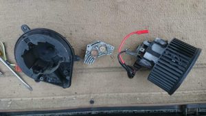
Once its out, pull the red and black motor connections from the electronics module. Looking at the side you’ll find three rectangular holes spaced equidistantly round the side. Push a flat screwdriver into each hole and gently pull the motor and fan assembly up out of the plastic. You’ll have to work around all three a few times but it will eventually prize out and you can guide the grommet and wiring through the plastic. Put the motor aside as we will look at this first, make sure the little rubber mounts do go astray. 3 screws hold the electronics to the plastic and the aluminum module can be withdrawn. You should have something like this now…

There are a few known issues. The most common is a simply dead unit, in which case you *could* likely swap just the electronics from a known good unit and snap it all back together. However I feel there may be other things at play here.

Another known issue is for the blower motors to torch the fuse box. The most commonly posited reason for this is blocked pollen filters, however with no air to circulate the load on the fan should be less, not more, so this explanation makes little sense. However stripping my unit I spotted something else, the motor was not free to move, well not as free as it should be. Powering the fan up from a bench power supply put the supply into protection at a current way above what I expected, Ah-Ha! So first job was to degunk, clean and lubricate the bearings. The top one is easy enough to do, the bottom one, less so. The motor cannot be stripped any further so its a case of the best you can do. Light machine oil was used on the bearings and some graphite grease to lube the brushes. The motor now not only span easier but drew significantly less current and was quieter. I would pin the fuse box burn outs on stiff motors before filters. As the whole lot comes apart easy enough this is a simple job to do “just in case”

On to the electronics….


ZBD EPOP Blade-C E-Ink Displays – Part 2 1/2 – Custom Code & EEPROM

Well not a real update as such, but an interesting milestone.

Using the MightyCore package I’ve managed to get the Arduino bootloader up on one of these boards.  Using a USB ASP the bootloader flashed ok. There is something screwy with the serial port bits as the baud rate and speeds are way out of whack. I suspect its an oscillator setup issue as the timing loops are running way too fast, Aprox 7 times too fast and given we have a 7 Mhz Oscilator and arduino thinks we are running at 1Mhz its a safe bet. I’ll have a pop at changing the 7MHz osc for an 8Mhz and see what can be done to get this happy.

Still it means that in theory all the pins are available to me. I have the top drivers traced out. I’ll work out how to make the resultant drawing legible at some point.

It also turns out that the serial number is in the ATmega’s EEPROM. This would imply that the modem is a complete stand alone unit that’s simply sending and receiving data, kinda leaves the path open to making these talk to each other.

ZBD EPOP Blade-C E-Ink Displays – Part 2

Part 2 of this article.

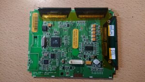
So popping the back of the case, just four screws, reveals this…

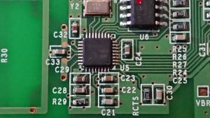
There really isnt much to the unit. On the pic of the front you can see a debug header at the bottom. this is duplicated twoce more on the reverse with a finer pitched connector AND a pin header. Quite why 3 copies were needed I don’t know but they are the exact same pinout. The front connection is a perfectly sensible size and pitch. This contains power, the uC’s serial and ICSP lines.

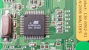
The uC is a well known and standard part that most will be familiar with from the Arduino range. That’s right, you *could* put the Arduino bootloader on here and if I can work out how to talk to the display it would effectiveley be possible to roll your own display controller.  As we have no specs on the LCD itself this is non trivial. Immediateley above it and hooked to the SPI bus is 1Mbit of NOR flash. The crystal is 7.3728Mhz which may have been chosen to make things a bit easier on the UART, although there is no real need to do this.

Below this is a Nordic Semi nRF9E5 RF SOC based on an 8051 core. Nordic Semi push this as a device for operation in the 433/868/915Mhz ISM bands. Given that only 433 is allowed in the UK (and europe I beleive) and looking at the antenna provided that’s where this will live. I can check this quickly enough with my SDR if I get time. however I’m not THAT interested in the radio at this time. These do answer back as the controller will complain if it sees no reply so these are full blown tranceivers and it may be possible to utilise them. The circuitry is quite well separated from the rest of the design suggestion it may have originated as a development board. RX, TX and CTS are labelled on the board, as are three other signals, BE, ARE and RWU. Quite what these are I don’t know however I would suspect there is at least one enable signal there.

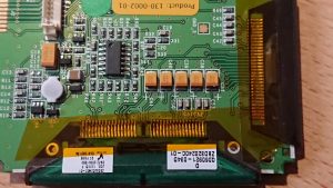
This seems to be power supply territory. A bog standard LP324 op amp lives in the middle and then there are a good spattering of caps and an inductor here and what looks like a controller. This needs metering out when the display is doing something. The ribbon on this side seems mostly dedicaed to power with many pins linked. There is an IC buried in the flat flex here too so it’s not quite that simple. I would imagine this is power supplies and row select with the upper ribbons handling the columns.

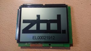
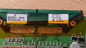
A close up of the display labels. The model number throws up a pdf : datasheet

This gives us something to go on, we have pin names and potentially the driver chips. We also have the display voltages, 3-5V for Logic and 15-20V for the display! Hence the power supplies.

The drivers seem to be referred to as ‘TAB’s and a quick look for the controllers listed not only gives the chip, but the flat flex layout in the datasheet. So for the top two tabs:
477731_1

And the side one:
393920_1

The top two cover 160 columns each and the side, 240 giving is a resolution of 320*240 which nmatches the image size the software asks for and the model of the display. Hopefully this provides what we need to drive the LCD itself, with out the need for constant refresh there is probobly less speed contraint on the scan time and indeed the scan does seem very slow when its refreshed. A quick check with a meter implies that the pinouts of the displays matches that of the tab. It also suggests that the NT7701s are cascaded as per the datasheet.

This gives us an 8 bit wide interface with 4 control lines and a clock. All of a sudden the idea of driving the display direct seems a little less daunting. With the large SPI EEPROM on board it should be possible to implement a char gen, although the limited RAM may be an issue. If we assume we use one byte per block of 8 pixels thats 320*240/8 = 9600 bytes or 10K of your 16K of RAM on the 16L8. If we are running as a display controller and nothing else this should be plenty. As we are only updating the display when it needs to change there is no need for double buffering etc.

A little update here: Part 2 1/2 – Life!


Outlook 2016 Password Silliness and Unable to Add New AD Accounts

I have seen this all over the web and no one had the answer that worked for me untill I found a clue hidden in an update.

The Symptoms are (in my case)
Outlook 2016 Suddenly (after an update) Starts asking for a password, although it seems to take the password and username eventually on some machines, more often than not it’ll keep asking.
In this case we are using Exchange 2010. There are a mixed bag of machines on the network and its only the 2016 machines that are doing this. Most of the time cancelling the dialog would make Outlook behave for a while but one or two machines were behaving oddly.

Reset everything in credential manager, forced the autodection via registry, rebuilt the profiles (More on that in a sec), reset passwords, reinstalled Office, tried a fresh install in fact NOTHING worked.

When we created new profiles we could not get them to work, they would not log in no matter what we tried, however OWA was fine with the same details.

At this point we are three months in…

So a few days ago with the intention of doing something else entireley I looked a bit deeper. Rand the connection diagnostics and noticed that was coming back clear. Isolated the machine from the net and BOOM! Prompt gone, Outlook goes back to normal. Allow access to the net again and the prompt is back. So some sniffing at the firewall and Outlook is talking to something at Microsoft prior to even looking at the AD/Exchange servers. A red flag is coming up at this point.

Office 16.0.6741.2017 Added support for something called Direct Connect to Office 365. A few people flagged up that during migrations this ‘Feature’ can screw up where Outlook goes to get mail and cause all manner of stuff ups. The reccomendation is that during a migration you set a registry key:

HKEY_CURRENT_USER\SOFTWARE\Policies\Microsoft\office\16.0\outlook\autodiscover
DWORD: ExcludeExplicitO365Endpoint
Value = 1

So I set this key and bam! Again, Outlook is behaving. Then it dawned on me. When 365 launched it was being given away like candy by a number of businesses including BT. Both sites where I’ve seen this they are/were BT customers and both had been given free 365 accounts. These accounts were long defunct but aparently still there. As we migrated them to AD and Exchange the email addresses would be the same, of course we changed the passwords for most, but not all. Where the passwords were not changed the login would work, Outlook would behave normally but things like checking for email automatically or calendar events were not quite right. Changing the password on one of these accounts broke it like the others. Disabling the “feature” put everything back to normal.

So the new profile I created for myself didn’t work because I had never had an account on 365, Outlook was trying to log into the now no good account for the customers’ domain with details that never existed and failing then not even trying AD. When the registry change was installed I could setup a new account.

Long story short, it seems that MS didnt think that people would ever move away from 365, and by assuming that O365 is ALWAYS authoritative over internal AD and DNS it means that anywhere 0365 has been in place in the past on a domain, you are going to get this error. Of course if the domain has never had an account O365 just denies all knowledge and we fall back to AD without ever knowing.

I’m not sure when overriding settings put in place by an admin became a good idea, but its just another part of the huge train wreck that Microsoft QA has become.


SPA504G Reset

We were recently approached by a customer (They will remain nameless but are a charity) with a batch of Cisco SPA504G IP phones. These had been purchased in good faith and duly delivered. Only they had vendor lock in. The customer tried a few avenues and if you’ve done a lot of searching you’ll know that there are a dozen ways to unlock. Most of them rely on assumptions that the vendor has not done something. The method below worked in this case and goes a little further than other suggestions, however if there has been a certificate set you are out of luck. I know there are people looking at hardware unlocking but at this point I would suggest you gave up.

Firsty, an honourable mention to the provider, Gamma Telecom. An inital call to their support guy was very promising. He didnt see an issue, took some details and we looked at the wireshark dumps (with plain text SIP credentials) and worked out who they belonged to and that they were indeed retired phones and there wasnt an issue with us having them. He took my number and wandered off. Shortly he called back and said I needed to speak to someone else and told me the process to get through the labyrinthine voicemail system. Hopeful I did as instructed.

“No, absoluteley not, we cant give you that information” Thats as far as I got. Despite owning the phones legally the rather rude woman wouldnt even listen to anything we asked. Explaining they were for a charity got no leeway at all. I even suggested the reprovision them and push a reset out that way. The phone went down.

SO here’s what was needed.

The phone gets plugged into my lab setup, its behind its own firewall there and I can control and manipulate everything. It turns out some simple DNS hacks were all that were needed. So watching the phone with wireshark, it asks for an IP, great, it’ll take the TFTP server and try that, no, no dice. It then asks right away for a SRV record from the provider. Ah-HA! I cant change the SRV record at this point, but a quick dig shows that it will ALWAYS return the same hosts, node7 and node4.sip.unlimitedhorizon.co.uk. Host overrides entered in PFSense and the phones start trying to register to my Freepbx lab server. They get denied, but it means I have some control over the damn things.

At this stage I’ve been puzzling over this for a while and then I spot something. When the phones dont get a response or are told to go swing by those servers they sit there in a loop retrying. HOWEVER a login failure rather than a refusal triggers something else. Hot on the tails of both servers failing the login it then tries to connect to an HTTP server, xsp.unlimitedhorizon.co.uk and it asks for /dms/Cisco_504d/<mac>-Recovery.xml A manual browse over there gets nothing, however tweeking the mac address results in firmware images being served. There’s some big security issues here, least being that I suspect its possible to take over another phone by flashing that image to another unit. For us this means that we have an in.

This Site suggests that you can serve an xml file to it. You can then force the phone to pull the file. However if the web UI is locked that wont work and if it’s also not looking for TFTP servers it wont work either. So, I added another DNS override to point that host to one of my servers, uploaded that file, renamed it to match what the phone was asking for and rebooted.

File gets requested and sent, all looks good, phone then ignores the file and switches to trying to use TLS for an update. Uh oh I’m stuffed here. I cant spoof the cert. I can see it failign as it doent like my server cert’s CA. What now.

I have an SPA504G on my desk, I know you can dump the XML so off I go and do just that. A quick look at the XML shows that the MAC is included, so thats edited to match the locked phone and the admin password line from the above xml is added. We reboot again…

Asks for the file…
Grabs the whole damn thing…
Reboots. On reboot i’m greeted with a clone of my phone. A quick venture into the menus shows that the admin password has gone too. A quick factory reset which I can now do and its all up and running as it should. One clean, factory reset phone.

Now this presents a number of conclusions. Cisco are good at this, we’ve seen that if this DID resort to TLS and there is an option to do this, you would be screwed. That they didnt do this seems odd, its one setting, but in doing so they left it wide open. Everything else was set to make it as hard as possible to unlock the phone so why leave this back door wide open?

How much of a risk is that web server. I have five phones here with distict MAC ranges. I can take a good guess that phones would have arrived in batched and a search in a range and a quick text shows I can pull about 5 xml files that dont relate to me.

Its possible they have realised there could be an issue here as the XML files point to a .bin file, the file freely downloads which raises the question of what it is, and can I flash it to anything? I knwo I can force the phones as they stand into arbitary configurations, can these files then be written to a phone to hijack that ‘line’? I’m not willing to risk the customers phones but it does raise the question of security of the system as a whole.

UPDATE

The XML I used from my own phone is here, you use these files at your own risk!

Cisco_504d XML Files