Hacking the Audi Concert Pt 4 – Front panel display, Radio and RDS modes

The next thing to look at is how the display deals with the above three modes. Although we wont be using these modes they do show how we may be able to get a few extra bits that we can use.

Radio mode is actually REALLY simple. For some reason though my head unit wont stay in AM mode so I wont cver it but it should be pretty similar. I susect there is a variation on the tuning mode that will display the right steps. I also dont have the telltale codes as I cant actually see them on my display 🙁

We are interested in the code 0x09A,  0x02, 0xaa, 0xbb. This seems to put the display in frequency mode and then displays the frequency in steps of .1MHz from 87.5 so for example 0x01 would be 87.6Mhz. 0xbb is always set as zero but it may be this is used for AM mode.

0x9A, 0x13 is issued just before, I dont think this is mode switching but likeley refers to setting of the telltales. It does seem this is used with every LCD mode change however I have noticed the micro does update the screen whenever it can rather than when needed.

Now the fun (and useful) one. RDS mode. This seems just as simple as above. On switching from frequency mode to RDS mode we see the following commands…

0x9A, 0x02, 0xaa, 0x00 – Freq display refresh, not sure why this is sent
0x9A, 0x23, 0x00, 0x00, 0x00 – Clear display
0x9A, 0x48,0xnn……

Why we are updating the frequency then clearing the display I really dont know. But once the display is clear the head unit sends the station ID as text. The bytes 0x9A and 0x48 are followed by 8 characters as their ASCII codes. If the ID is less then it is padded with 0x20 (space). Exactly what characters are valid is unknown. It should be possible to implement scrolling though as the display updates very fast. It may be possible to skip the clear to make it smoother.

Next: Tape Mode
 

Hacking the Audi Concert Pt 3 – Front panel, display & code entry

So we have out unit unlocked. We have the keypad protocol now time to see how the diaplay works. The keypad never changes its behaviour so the previous section applies and I wont show the keyboard data.

It seems that there are at least 4 modes :

“SAFE” this simply displays the word SAFE and nothing else.

“TAPE” Likewise although there are two direction indicators that show

Text mode. This allows freeform text. There are a number of legends too that sadly cant be seen on my display.

Radio Mode. This displays a frequency. It seems to take an 8 bit step number which the display translates.

All commands to the display start with 0x94, there then follows a command byte and the various commands seem to have different lengths. As with the keyboard there is no CRC generation.

“Safe” mode: Assuming you’ve powered up your radio from cold and its been out of the car a while AND its not had the code disabled (some seem to) you’ll be presented with a screen that says SAFE. This is the code entry screen and it seems to be one of a number of stored screen modes.  We see the following commands at boot into safe mode:

0x25, 0x25 : Init from keypad

0x09, 0x61,  0x0B sent along with 0x13, 0x40, 0x00, 0x00 right after. 0x13 is LED and LCD teltale command and this sets a single bit so its possibl this is what actually sets the SAFE display, HOWEVER 0x09 controls the tape direction telltales so this could also be involved here. Until I’m able to extract the codes for the Teltales which will mean being able to see them, I cant be sure what the LED command is doing here. I do plan on sending some of these commands to the display to see what happens so that may help here too. Pressing and holding RDS and TP will send keycode 0x1E and the micro issues a new sequence of commands:

0x9A, 0xE1, 0xFB – No idea what this does.
0x9A, 0x61, 0x0B – This apears to activate the SAFE display.

Once this sequence is done, the second sequence is resent  every 2S. Pressing and holding RDS+TP to go into code entry gets the following:

0x9A, 0x13, 0x40, 0x00, 0x00 – 0x13 IS led control. Byte 3 is LCD telltales as far as I can see.
0x9A, 0x23, 0x00 ,0x00 ,0x00 – LCD Clear
0x9A, 0x92, 0x10 ,0x00 – This is code entry mode. the last 4 nibbles are the currently displayed code. so in this case 1000.

Hitting 1,2,3 or 4 to change the code now will resend the above command with the nibbles altered. eg, if you hit 2 twice you’ll get

0x9A, 0x92, 0x12 ,0x00

Pressing and holding TP+RDS will either start a normal boot (next page) or restart the whole process.

On to RDS and Radio modes


Hacking the Audi Concert Pt 2 – Front panel, Keypad

SO into deep hack. I want to be able to talk to the front display and buttons. Although I plan to replace the deck this doesnt give me all the buttons I might want. A quick poke shows that I get 3 buttons to work with if I pick the deck commands up as is. I’d like more and I’d also like the front panel to say something other than ‘TAPE’

The Concert and Chorus are more or less the same thing so the manual here covers both. A quick look shows us we want X1001 (The front panel connector) and in particular pins 2, 3 and 4. These compose the SPI interface to the panel. With my analyser set for Active low clock, validon  leading edge and enable (status) active high I’m able to see whats going on.

Now I’ve only been looking at these three lines and something that is imediately of concern is that the schematis shows these as unidirectional TO the display. I beleive this to be an error.  Status is shown as originating from the display, again, I’m not sure on this one.

Watching the exchange its imediately clear that there is a simple command set in use here. The first byte seems to specify if the data of coming from the keypad or to the display. The keypad is pretty simple.

The first byte is always 0x25 followed by a key ID. A key up is sent when a key is released (0x21).

The keycodes apear to be:

0x01 – 1
0x02 – 2
0x03 – 3
0x04 – 4
0x05 – 5
0x06 – 6
0x07 – Seek >
0x08 – TP
0x09 – RDS
0x0A – CPS
0x0B – MODE
0x0C – <<
0x0D – FAD
0x0E – BAL
0x10 – BASS
0x11 – AM
0x12 – Dolby
0x13 – >>
0x14 – TREB
0x15 – AS
0x16 – SCAN
0x17 – FM
0x18 – Seek <
0x19 – REV
0x1A – Knob +
0x1B – Knob –
0x1E – Code in (TP+RDS)

There may be others but this seems to cover most. Interestingly the controller is pretty dumb, switching to tap or CD doesnt diable the unused button, the micro on the board just ignores it. This means intercepting these unuded keys should be trivial enough giving full use of ALL buttons.

On boot the keypad does send 0x25, 0x00 which seems to be a message stating that no keys are down at boot. I’ll verify this.

So in summary for the keypad, this all looks very simple to get to. I could now simply drop into tape mode as per the original firmware and be done but as I plan to have both bluetooth and MP3 built I’d like more functionality and that means the display.

So, on to the display…

Hacking the Audi Concert

My latest aquisition is an Audi A6 2.8 Quattro. Of the many really nice bits of thought that Audi put into this was the flap that covers the head unit. Like many I like as little light in the cabin as possible as night so I thought this was great. Sadly the Alpine head unit, which is Awesome) that has been fitted after market sticks out too far, you cant close tha flap. In fact a quickl look shows that most manufacturers insist in a stupid, huge control knob, so there is nothing that will drop in. I’d also like to keep is stock and get the dash display back. So off we go looking….

Exhibit 1, the Concert 2. This is CD rather than Casette but requires a CAN bus equipped car. The facelist A6 B5 does support this and this is the radio in those cars. It supports the BOSE audio system in mine, should make the dash work and supports multiple inputs (CD Changer, Nav, Phone) So should be hackable for bluetooth and Line in. I obtained a CAN adaptor and off we went…..

No Dash screen. Seems the Concert 2 wants to chat to the dash screen over CAN, not the FIS interface my car had. Bugger. This is fixable with a different CAN adaptor to the one I have. It shouldnt be a huge thing to make a convertor. A bigger pain is despite being the radio fitted in the facelift car it physically doesnt fit. You have to press both controls in and then close the flap which will turn the radio back on as it presses the tops or turns it off. Close but no cigar.

So Option 2. Hack a concert. Having otained one I hit the first big snag. Unless you have the code you are stuffed. Working concerts with the code and working volume controls are few and far between.  I’ve stripped it down and decided there are a few ways to do this but by far the easiest is the realisation taht the tape unit is not only a module but its largeley independant with its own MechCon board. As this is a logic driven deck its very likeley this board simply takes commands from the main MCU in the form of play/stop/rev/etc. Having found a schematis the audio out from the head pre-amp is easy to get to as well so a drop in board is a possiblilty.

The MCU uses a large number of serial busses which are a mix of SPI, I2C and RS232 and each section of the radio is a clearly defined block so there are a large number of possibilities here.

First goal is to get this bugger unlocked. I have the dev kit for the Micro they chose (Its been in storage for years because I thought it may be useful) so I’m planning on sucking its brains out and pulling the code out. I’m also chasing Audi who, in the manual, insist its a free service but the main stealers want £50 to get the code.  Audi UK are chasing this for me. Given that locked ones can be found easilly it may be a better bet to work out how to get it myself.

http://kovo-blog.blogspot.co.uk/2015/08/audi-chorus-concert-how-to-recover.html

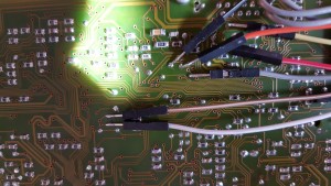
Gives some pointers on how to do it, so I guess this is the first stop. I modified a cheap CH340 dongle and using that circuit pulled the code out first time. Not only can you do this WITHOUT removing the micro Audi/Blaupunkt left test pads for all of these connections under the board…

Concert EEPRON recovery
Concert EEPROM recovery

Its worth noting at this point that it *should* be possible to suck the ROM contents out too. I’m not sure if this version of the chip uses EEPROM or Mask ROM/EPROM for the main program. Armed with a disassembler it should be possible to fix the actual bug. You can also use the MotoHack tool to change the keycode or disable it. I opted to leave well alone as I dont know if there is a checksum in there or not.

Having pulled the cod I confirmed it does work and unlocked the unit. Turns out my display is a little dead but for our purposes its good enough. Off we go now to decipher the front panel…

Next: Keypad Hacking