ZBD EPOP Blade-C E-Ink Displays – Part 2 1/2 – Custom Code & EEPROM

Well not a real update as such, but an interesting milestone.

Using the MightyCore package I’ve managed to get the Arduino bootloader up on one of these boards.  Using a USB ASP the bootloader flashed ok. There is something screwy with the serial port bits as the baud rate and speeds are way out of whack. I suspect its an oscillator setup issue as the timing loops are running way too fast, Aprox 7 times too fast and given we have a 7 Mhz Oscilator and arduino thinks we are running at 1Mhz its a safe bet. I’ll have a pop at changing the 7MHz osc for an 8Mhz and see what can be done to get this happy.

Still it means that in theory all the pins are available to me. I have the top drivers traced out. I’ll work out how to make the resultant drawing legible at some point.

It also turns out that the serial number is in the ATmega’s EEPROM. This would imply that the modem is a complete stand alone unit that’s simply sending and receiving data, kinda leaves the path open to making these talk to each other.

ZBD EPOP Blade-C E-Ink Displays – Part 2

Part 2 of this article.

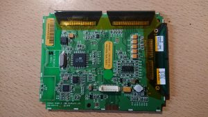
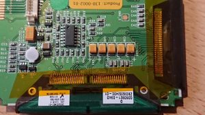
So popping the back of the case, just four screws, reveals this…

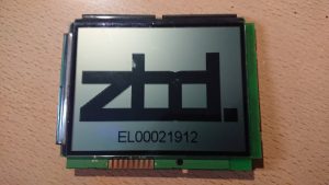
There really isnt much to the unit. On the pic of the front you can see a debug header at the bottom. this is duplicated twoce more on the reverse with a finer pitched connector AND a pin header. Quite why 3 copies were needed I don’t know but they are the exact same pinout. The front connection is a perfectly sensible size and pitch. This contains power, the uC’s serial and ICSP lines.

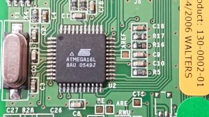
The uC is a well known and standard part that most will be familiar with from the Arduino range. That’s right, you *could* put the Arduino bootloader on here and if I can work out how to talk to the display it would effectiveley be possible to roll your own display controller.  As we have no specs on the LCD itself this is non trivial. Immediateley above it and hooked to the SPI bus is 1Mbit of NOR flash. The crystal is 7.3728Mhz which may have been chosen to make things a bit easier on the UART, although there is no real need to do this.

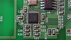
Below this is a Nordic Semi nRF9E5 RF SOC based on an 8051 core. Nordic Semi push this as a device for operation in the 433/868/915Mhz ISM bands. Given that only 433 is allowed in the UK (and europe I beleive) and looking at the antenna provided that’s where this will live. I can check this quickly enough with my SDR if I get time. however I’m not THAT interested in the radio at this time. These do answer back as the controller will complain if it sees no reply so these are full blown tranceivers and it may be possible to utilise them. The circuitry is quite well separated from the rest of the design suggestion it may have originated as a development board. RX, TX and CTS are labelled on the board, as are three other signals, BE, ARE and RWU. Quite what these are I don’t know however I would suspect there is at least one enable signal there.

This seems to be power supply territory. A bog standard LP324 op amp lives in the middle and then there are a good spattering of caps and an inductor here and what looks like a controller. This needs metering out when the display is doing something. The ribbon on this side seems mostly dedicaed to power with many pins linked. There is an IC buried in the flat flex here too so it’s not quite that simple. I would imagine this is power supplies and row select with the upper ribbons handling the columns.

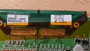
A close up of the display labels. The model number throws up a pdf : datasheet

This gives us something to go on, we have pin names and potentially the driver chips. We also have the display voltages, 3-5V for Logic and 15-20V for the display! Hence the power supplies.

The drivers seem to be referred to as ‘TAB’s and a quick look for the controllers listed not only gives the chip, but the flat flex layout in the datasheet. So for the top two tabs:
477731_1

And the side one:
393920_1

The top two cover 160 columns each and the side, 240 giving is a resolution of 320*240 which nmatches the image size the software asks for and the model of the display. Hopefully this provides what we need to drive the LCD itself, with out the need for constant refresh there is probobly less speed contraint on the scan time and indeed the scan does seem very slow when its refreshed. A quick check with a meter implies that the pinouts of the displays matches that of the tab. It also suggests that the NT7701s are cascaded as per the datasheet.

This gives us an 8 bit wide interface with 4 control lines and a clock. All of a sudden the idea of driving the display direct seems a little less daunting. With the large SPI EEPROM on board it should be possible to implement a char gen, although the limited RAM may be an issue. If we assume we use one byte per block of 8 pixels thats 320*240/8 = 9600 bytes or 10K of your 16K of RAM on the 16L8. If we are running as a display controller and nothing else this should be plenty. As we are only updating the display when it needs to change there is no need for double buffering etc.

A little update here: Part 2 1/2 – Life!


ZBD EPOP Blade-C E-Ink Displays – Part 1

Please note – We have asked ZBD’s new owners foir this info. As we have so many of these I’d rather they were not junked and pushed into service for other things. The company hasn’t even seen fit to reply to me 🙁

So we often work with a local IT recycler. It’s become a thing whereby when anything odd or unique comes in, I get a call. One of these calls let me to a ton of Electronic Point of Sale Displays. These were trialled in a number of places over the world and never really caught on. The economics of the system were dodgy at best and now these units have aged a bit there are a few issues that in a retail environment could be an issue. If you’d like to read up on these a little and see how they work theres a little bit of info here.

https://www.cdmconsultores.com/cms/images/files/ZBD_EPOP_500.pdf

https://fccid.io/VC7120-0081/User-Manual/Manual-1495810

Now I have a few hundred of these…

The display itself, even if it were an LCD would be worth saving, however its something more. The display is a bistable display based on Cholesteric technology this means once you have written to it, the display does not require refreshing by thge controller. This means your controller can write the display, then go into deep sleep using uA of power. This is ideal for things that don’t need to update that frequently and/of are running on limited power. The display isn’t grayscale cabable but the pixel size is fine enough to allow dithering.

The displays are updated via radio and I was lucky enough to not only get the tranceiver, but the software as well and some demo software so I can write to these. And thats where the first two problems show up.

First up, the Lithium primary cells are all but dead in most of these. They are simple 3V packs so its not a huge issue.

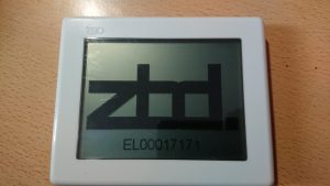
Secondly, these seem to show an element of burn in. I have not found a solution for this yet so some of these retain the test image they came with. It seems to vary from unit to unit as to how much of an issue this is.

Regardless I have a good stash of these and they are popping up on ebay, so finding out how to use them or at least recycle the panel, would be handy. I’ve had a little play with these before just poking about, but this post and the next few will document these things properly and see if we can’t find a structured way of getting inside them.

From the inital play around I suspect the software is simply feeding a bitmap image over the air, the displays have a programming header and well marked test points so I was able to obtain some data during an update so the next step is to unpick what is coming in and how the software communicates.

The next part will contain some images and a look at the display hardware.

On to Part 2

Musings…

I keep forgetting this blog is even here, moreover I’m impressed people actually read it. I know I have not kept up to date with comments and things on here, mostly because I didnt realise people read it!

So for 2019 I’m going to try and keep this up to date a bit more and interact with you guys.  We have a lot going on in the next few months including some big changes over here so it’ll be interesting to get the challenges up here in the open.

Although I don’t and wont share personal contact details here, you can find our company facebook page at https://www.facebook.com/realitytechportsmouth/

Au Revoir!

Outlook 2016 Password Silliness and Unable to Add New AD Accounts

I have seen this all over the web and no one had the answer that worked for me untill I found a clue hidden in an update.

The Symptoms are (in my case)
Outlook 2016 Suddenly (after an update) Starts asking for a password, although it seems to take the password and username eventually on some machines, more often than not it’ll keep asking.
In this case we are using Exchange 2010. There are a mixed bag of machines on the network and its only the 2016 machines that are doing this. Most of the time cancelling the dialog would make Outlook behave for a while but one or two machines were behaving oddly.

Reset everything in credential manager, forced the autodection via registry, rebuilt the profiles (More on that in a sec), reset passwords, reinstalled Office, tried a fresh install in fact NOTHING worked.

When we created new profiles we could not get them to work, they would not log in no matter what we tried, however OWA was fine with the same details.

At this point we are three months in…

So a few days ago with the intention of doing something else entireley I looked a bit deeper. Rand the connection diagnostics and noticed that was coming back clear. Isolated the machine from the net and BOOM! Prompt gone, Outlook goes back to normal. Allow access to the net again and the prompt is back. So some sniffing at the firewall and Outlook is talking to something at Microsoft prior to even looking at the AD/Exchange servers. A red flag is coming up at this point.

Office 16.0.6741.2017 Added support for something called Direct Connect to Office 365. A few people flagged up that during migrations this ‘Feature’ can screw up where Outlook goes to get mail and cause all manner of stuff ups. The reccomendation is that during a migration you set a registry key:

HKEY_CURRENT_USER\SOFTWARE\Policies\Microsoft\office\16.0\outlook\autodiscover
DWORD: ExcludeExplicitO365Endpoint
Value = 1

So I set this key and bam! Again, Outlook is behaving. Then it dawned on me. When 365 launched it was being given away like candy by a number of businesses including BT. Both sites where I’ve seen this they are/were BT customers and both had been given free 365 accounts. These accounts were long defunct but aparently still there. As we migrated them to AD and Exchange the email addresses would be the same, of course we changed the passwords for most, but not all. Where the passwords were not changed the login would work, Outlook would behave normally but things like checking for email automatically or calendar events were not quite right. Changing the password on one of these accounts broke it like the others. Disabling the “feature” put everything back to normal.

So the new profile I created for myself didn’t work because I had never had an account on 365, Outlook was trying to log into the now no good account for the customers’ domain with details that never existed and failing then not even trying AD. When the registry change was installed I could setup a new account.

Long story short, it seems that MS didnt think that people would ever move away from 365, and by assuming that O365 is ALWAYS authoritative over internal AD and DNS it means that anywhere 0365 has been in place in the past on a domain, you are going to get this error. Of course if the domain has never had an account O365 just denies all knowledge and we fall back to AD without ever knowing.

I’m not sure when overriding settings put in place by an admin became a good idea, but its just another part of the huge train wreck that Microsoft QA has become.